
Power tool having a clamping device for a working element

a technology of working element and clamping device, which is applied in the field of power tools, can solve the problems of not being able to ensure the clamping of the working element sufficiently and firmly by means of a known clamping device, the clamping device is only suitable for clamping the rotatably driven working element, and the transilient torque is greater, so as to achieve convenient and effort-saving use, reduce the effect of cost and simple and compact structur

Inactive Publication Date: 2015-06-23
CHERVON HK LTD WANCHAI
View PDF5 Cites 16 Cited by
  • Summary
  • Abstract
  • Description
  • Claims
  • Application Information

AI Technical Summary

Benefits of technology

[0005]To improve upon the deficiencies noted in the above prior art, the present disclosure provides a power tool, which can fasten the working element to the output shaft in a simple and reliable manner without the use of such auxiliary tools as a spanner etc. and can achieve a stronger clamping force. Even under impact conditions, which occur in the tool driven by a vibration driver, for example, this clamping force is sufficient enough to ensure the working element to be clamped reliably and firmly.
[0023]The power tool further comprises a disengagement-proof element for preventing the protruding shaft from falling out of the cavity.
[0031]By utilizing the above technical solution, the power tool according to the present disclosure has a quick clamping device for the working element, so its usage is convenient and effort-saving, and the structure is simple and compact, and the cost may be largely reduced.

Problems solved by technology

Though, for this kind of clamping device, the working element can be substantially clamped to the output shaft of the hand-held tool without any auxiliary tools, however, this clamping device is only suitable for clamping the rotatably driven working element.
If the working element is driven by a vibration device such that the working element sways forward and rearward along a longitudinal axis of the output shaft, then this results in a greater transilient torque and a very great impaction occurring in the two rotation directions and it is effectively impossible to ensure the working element to be clamped sufficiently and firmly by means of a known clamping device.

Method used


Image

  • Power tool having a clamping device for a working element
  • Power tool having a clamping device for a working element
  • Power tool having a clamping device for a working element

Examples


first example

A First Example

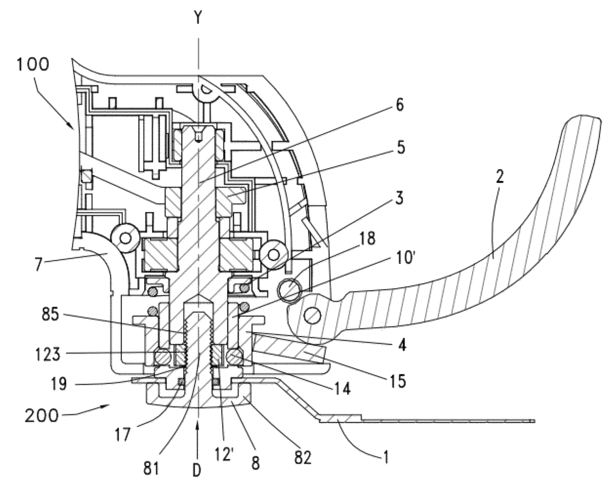
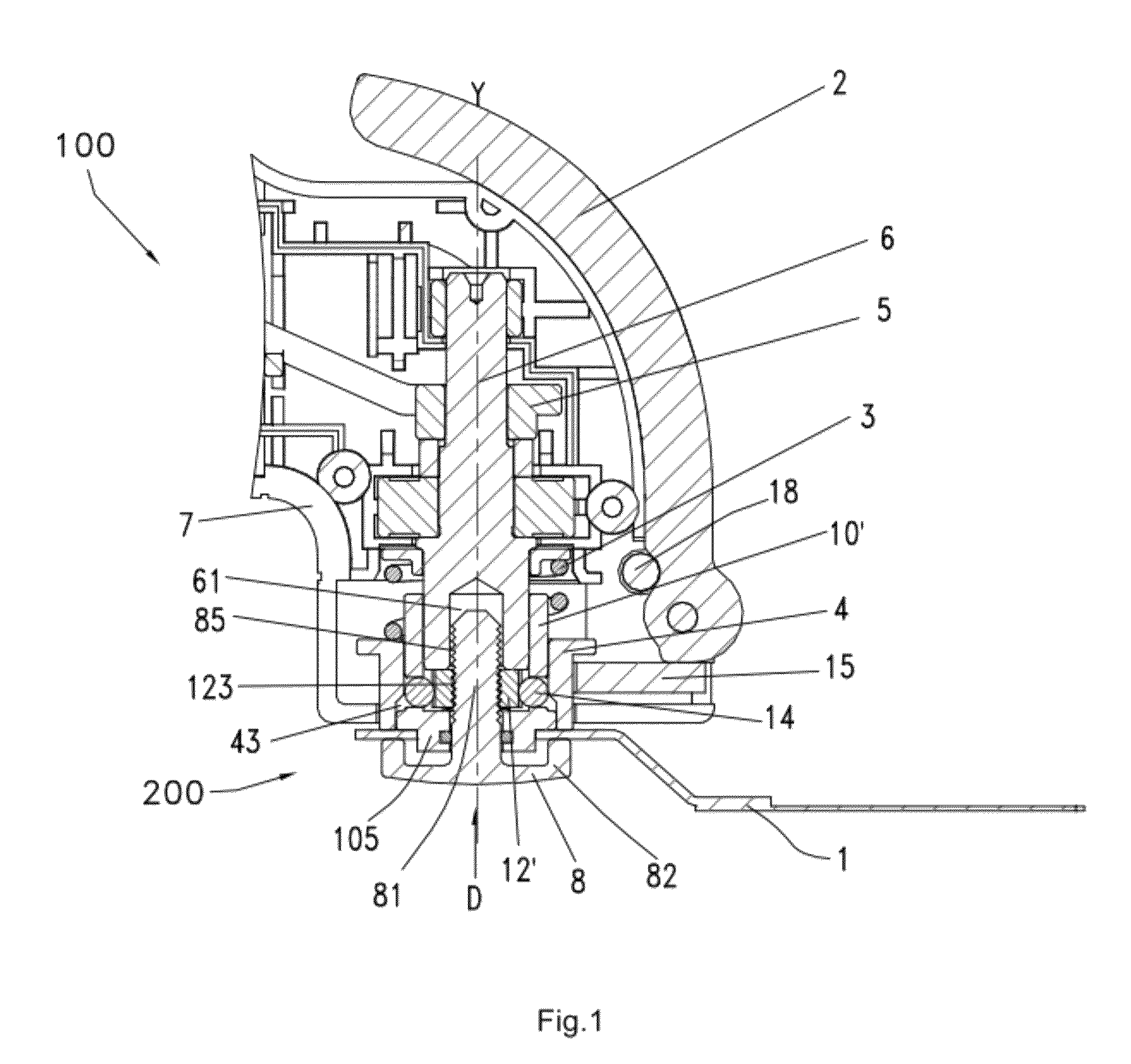
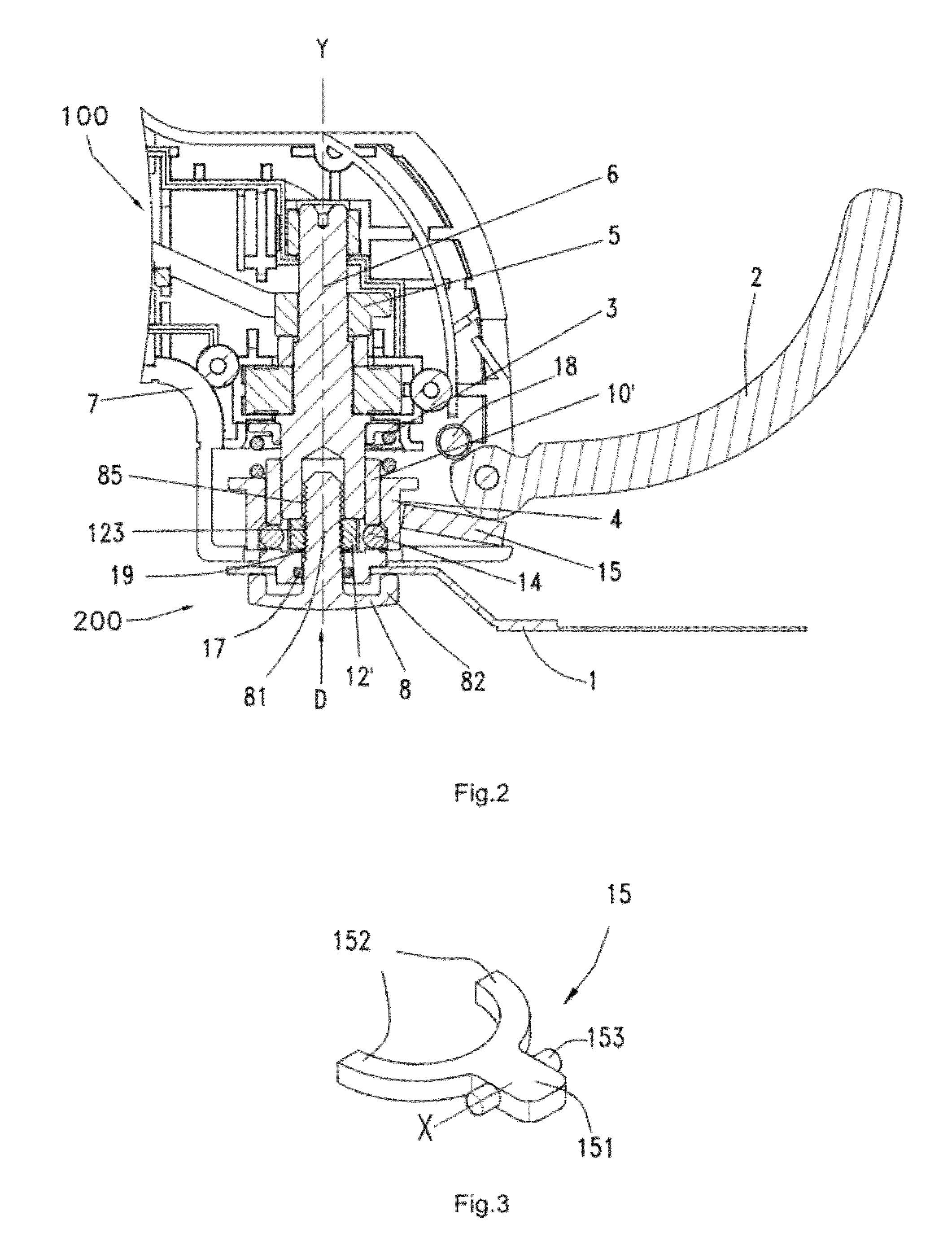
[0046]As shown in FIGS. 1, 2 and 6, the present disclosure will be illustrated with a power tool 100 as an example which drives a working element 1 in an oscillating manner. A power output shaft 6 of the power tool 100 is supported by bearings and sways back and forth about its axis Y with a small deflection angle and a high frequency under the action of a vibration bracket 5. The power output end of the output shaft 6 is connected with a clamping device 200 for clamping a working element 1. The clamping device 200 comprises a fastening piece 8, a pressing block 4 cooperating with the fastening piece 8 to clamp the working element 1, and a locking assembly for locking the fastening piece 8. The fastening piece 8 is configured to have a flange portion 82 able to clamp the working element 1 and have a protruding shaft 81 substantially perpendicular to the flange portion 82.

[0047]The locking assembly comprises a locking shaft 10′, a locking member 12′ and steel balls 14,...

second example

A Second Example

[0057]As shown in FIGS. 10 to 14, a power output shaft 6 of a power tool 100 is supported by the bearings and sways back and forth about its axis Y with a small deflection angle and a high frequency under the action of a vibration bracket 5. The power output end of the output shaft 6 is connected with a clamping device 200 that is used for clamping a working element 1. The clamping device 200 comprises a fastening piece 8, a pressing block 4 for cooperating with the fastening piece 8 to clamp the working element 1, and a locking assembly for locking the fastening piece 8. The fastening piece 8 is configured to have a flange portion 82 able to clamp the working element and have a protruding shaft 81 substantially perpendicular to the flange portion 82.

[0058]The locking assembly comprises a locking shaft 10, a slidable sleeve 11 and a locking member 12, wherein the locking shaft 10 is configured as a hollow member in which the hollow cavity 61′ is used for receiving th...


PUM


Abstract

The present disclosure provides a power tool having a clamping device for a working element. The power tool includes an output shaft, a fastening piece having a flange portion for clamping the working element and a protruding shaft substantially perpendicular to the flange portion. A locking assembly comprising a locking member having a first position in which the protruding shaft is locked and a second position in which the protruding shaft is loosened is provided, wherein a pressing member can press the working element between the pressing member and the flange portion when the locking member is in the first position. The power tool can fasten the working element to the output shaft in a simple and reliable manner without the necessary use of such auxiliary tools as a spanner etc. and can achieve a stronger clamping force even under impact conditions.

Description

CROSS REFERENCE TO RELATED APPLICATION[0001]This application claims the benefit of Chinese Patent Application Nos. CN201010515143.8, filed Oct. 9, 2010, and CN201010574780.2, filed Nov. 24, 2010, each of which are incorporated herein by reference in their entirety.FIELD OF THE DISCLOSURE[0002]The present disclosure relates to a power tool comprising an output shaft for driving the tool and a fastening piece for clamping a working element to an end of the output shaft. The tool further comprises a moving device for enabling the fastening piece movable between a released position and a clamped position. At the released position, the fastening piece can be removed from the output shaft by being disengaged from the moving device, and conversely at the clamped position, the fastening piece can lean against the end of the output shaft by locking with the moving device and cooperating with an elastic element such that the working element is firmly clamped.BACKGROUND OF RELATED ART[0003]A p...

Claims


Application Information

Patent Timeline
Patent Type & Authority Patents(United States)
IPC IPC(8): B23B31/10B23B31/19B25F5/00B27B5/32
CPCB25F5/00B23B31/19B23B31/10B27B5/32Y10T279/32Y10T279/33
Inventor ZHOU, HONGTAONI, GUIGONG
Owner CHERVON HK LTD WANCHAI
Learn More