Positive displacement pump with improved sealing arrangement and related method of making

Active Publication Date: 2015-06-23
AMPCO PUMPS
View PDF2 Cites 3 Cited by
  • Summary
  • Abstract
  • Description
  • Claims
  • Application Information

AI Technical Summary

Benefits of technology

[0006]An improved pump assembly is disclosed that offers improved serviceability. This is achieved by moving the primary sealing arrangement that seals the internal cavity of the pump when the rotors are in place forward, such that this sealing arrangement can be accessed and removed without disassembling the pump body from the gear case. Additionally, a secondary sealing arrangement is introduced that selectively seals the internal cavity of the pump when the rotors and the primary sealing arrangement are removed for service. This secondary sealing arrangement permits the surrounding equipment to be cleaned when the primary sealing arrangement is removed; however, during normal operation of the pump, this secondary sealing arrangement is not typically exposed to the fluid being pumped (as this is the function of the primary sealing arrangement) and does not form a seal.
[0009]As noted above, the pair of rotors and the pair of forwardly-positioned sealing arrangements are removable from the rotary positive displacement pump without removing the pump body from the gear case (which is time and labor intensive). However, even when the rotors are removed, seals are selectively formed by the rearwardly-positioned selective sealing arrangements that permit the surrounding equipment to be cleaned by passing liquid at high velocity through the rotor-less cavity without fluid leakage at the rear side of pump body where the pump body is attached to the gear case.

Problems solved by technology

For decades this has meant that, in order to service or clean portions of the pump, the pump would need to be subject to long periods of downtime in which the pump body would need to be removed from the gear case in order to access the seals.
This secondary sealing arrangement permits the surrounding equipment to be cleaned when the primary sealing arrangement is removed; however, during normal operation of the pump, this secondary sealing arrangement is not typically exposed to the fluid being pumped (as this is the function of the primary sealing arrangement) and does not form a seal.
When the pair of rotors are secured to the pair of shafts, then the pair of rearwardly-positioned selective sealing arrangements do not establish seals between the gear case and the pump body.

Method used


Image

  • Positive displacement pump with improved sealing arrangement and related method of making
  • Positive displacement pump with improved sealing arrangement and related method of making
  • Positive displacement pump with improved sealing arrangement and related method of making

Examples


Embodiment Construction

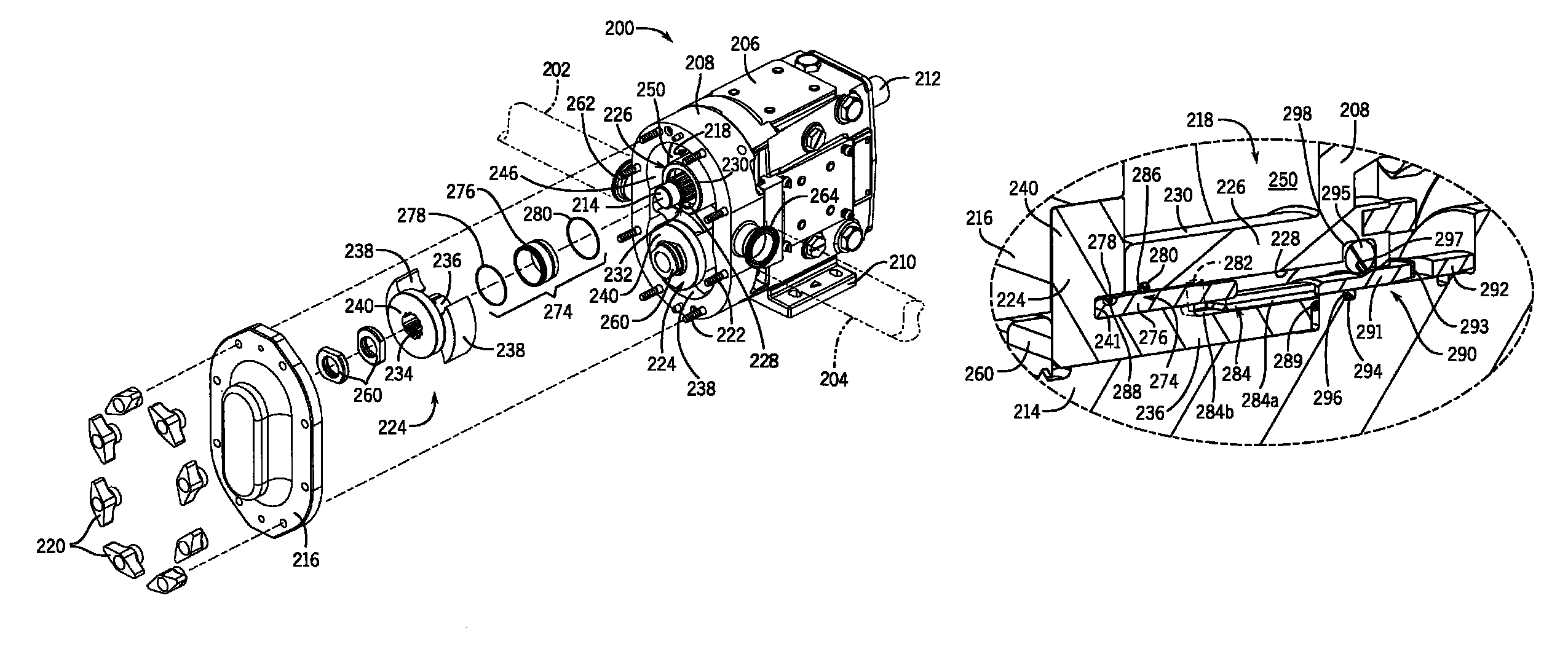
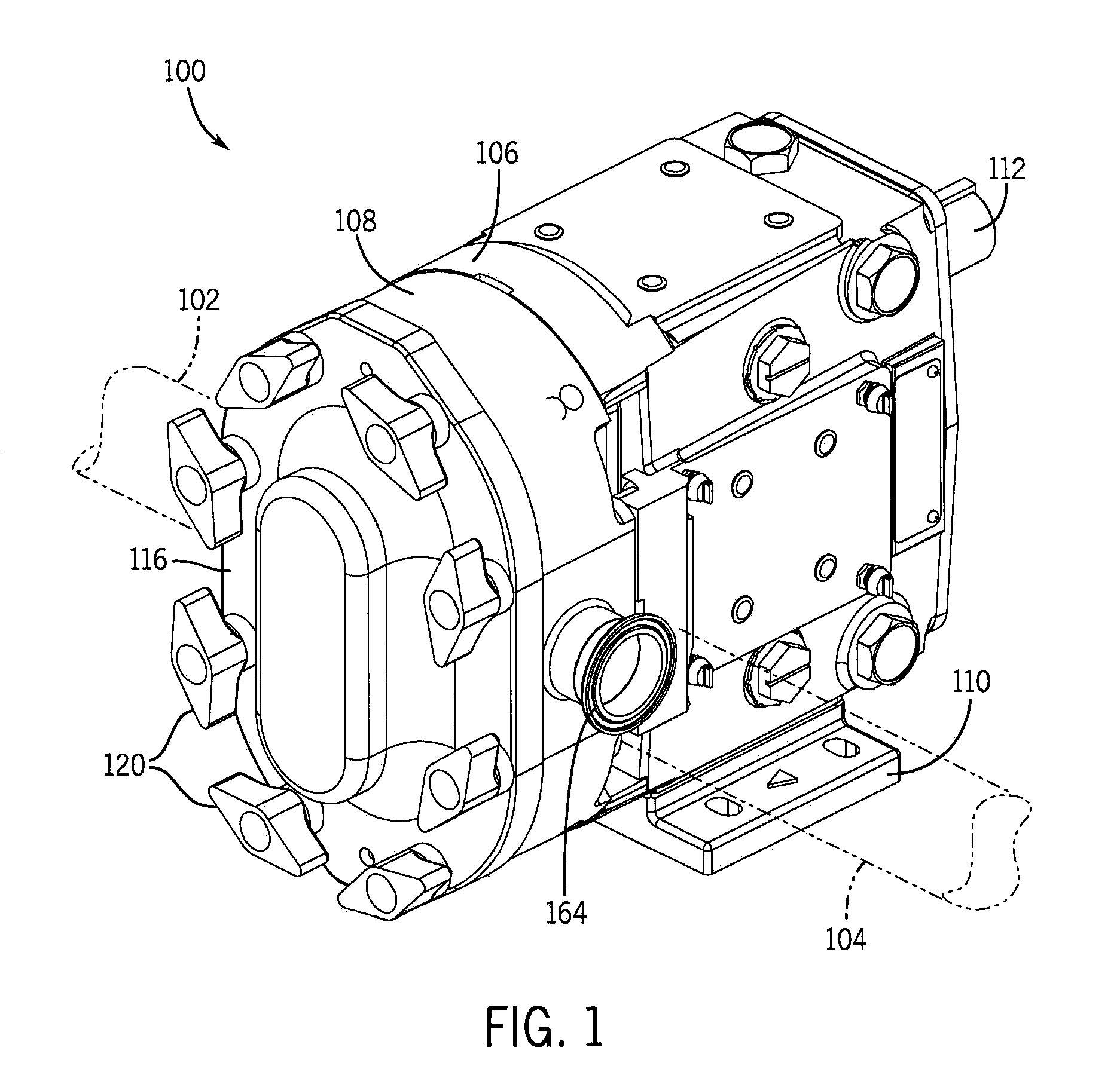
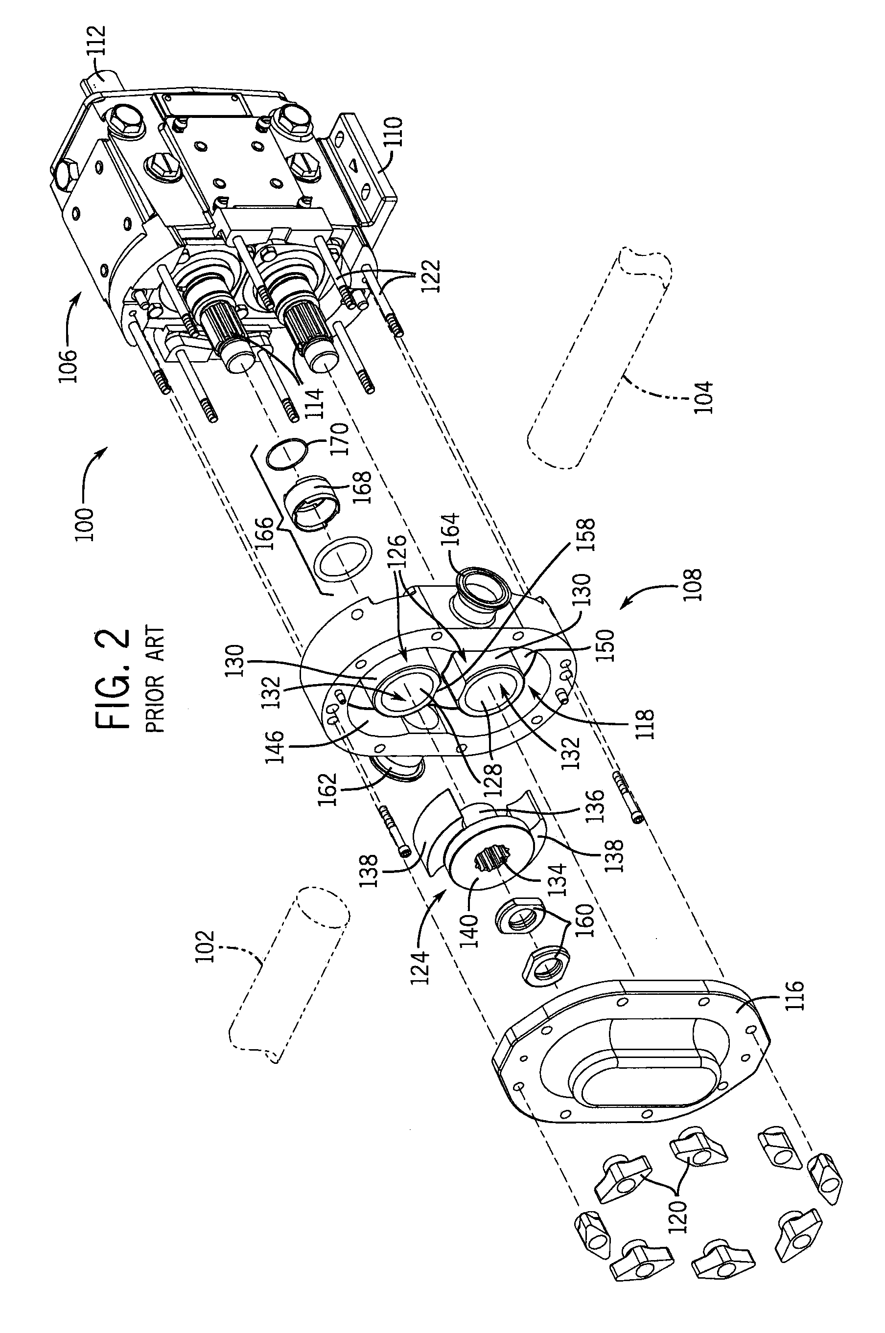
[0029]A rotary positive displacement pump according to one aspect of the invention will now be described in detail. Because the improved and modified version of the pump shares a number of common features with a prior art version of the pump, various figures are provided that illustrate the prior art pump 100 and the improved pump 200 for comparative purposes. A number of components or parts of the prior art pump 100 and the new pump 200 are similar; however, there are also differences between the prior art pump 100 and the new pump 200. Accordingly, the following detailed description is to be read with reference to the figures, in which like elements in different figures have like reference numerals. For example, component 108 (the pump body) in the prior art pump 100 will generally correspond in structure and function to the component 208 in the new pump 200. In the instances where differences exist between the prior art pump 100 and the new pump 200, those differences will be des...


PUM


Abstract

A rotary positive displacement pump comprising a pair of forwardly-positioned sealing arrangements and a pair of rearwardly-positioned selective sealing arrangements. The forwardly-positioned sealing arrangements each form a dynamic seal between a central portion of the one of the rotors and a corresponding hub proximate the forward ends of the shafts on which the rotors are received. The rearwardly-positioned selective sealing arrangements are located between the gear case and the pump body proximate the rearward ends of the shafts. When the rotors are secured to the shafts, the rearwardly-positioned selective sealing arrangements do not establish seals between the gear case and the pump body. However, when the rotors are removed from the shafts, the rearwardly-positioned selective sealing arrangements establish seals between the gear case and the pump body.

Description

CROSS-REFERENCE TO RELATED APPLICATIONS[0001]Not applicable.BACKGROUND[0002]This disclosure relates to rotary positive displacement pumps. In particular, this disclosure relates to improvements for rotary positive displacement pumps such as circumferential piston pumps.[0003]Pumps, such as rotary positive displacement pumps, can be used to transport fluids through a system. In a rotary positive displacement pump, two or more counter-rotating lobes are disposed in a cavity typically defined by a pump body and an associated cover. This cavity has an inlet on one side of the rotary lobes through which the fluid material is initially received and an outlet on the other side of the rotary lobes through which the fluid material is forced out of the pump. A gear case, which typically supports the pump body, has shafts that attach to the rotors. When the gear case drives the rotation of these shafts, the attached rotors rotate, thereby causing the pumping action.[0004]Although positive disp...

Claims


Application Information

Patent Timeline
Patent Type & Authority Patents(United States)
IPC IPC(8): F04C15/00F04C2/12F04C18/08
CPCF04C15/0038F04C2/12F04C15/0061F04C2230/70
Inventor GARNER, BOB
Owner AMPCO PUMPS
Why Eureka
Try Eureka