Supercharge Your Innovation With Domain-Expert AI Agents!

Integrated transformer with multiple transformation ratios

a transformer and transformer technology, applied in the direction of coils, inductances, antennas, etc., can solve the problem of large space consumption in the integrated circuit and achieve the effect of reducing the cost of the integrated circui

Inactive Publication Date: 2015-06-23
ST ERICSSON SA
View PDF4 Cites 0 Cited by
  • Summary
  • Abstract
  • Description
  • Claims
  • Application Information

AI Technical Summary

Benefits of technology

[0018]This allows obtaining different transformation ratios on the surface area occupied by a single inductor.

Problems solved by technology

A large amount of space is therefore consumed in the integrated circuit, as each antenna stage requires a circuit that has a transformer.

Method used


Image

  • Integrated transformer with multiple transformation ratios
  • Integrated transformer with multiple transformation ratios
  • Integrated transformer with multiple transformation ratios

Examples


Embodiment Construction

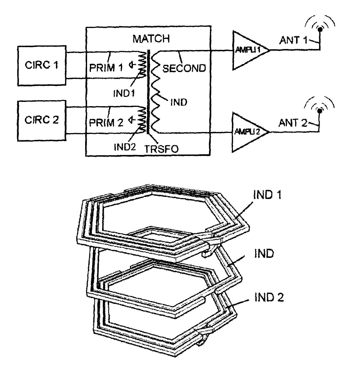
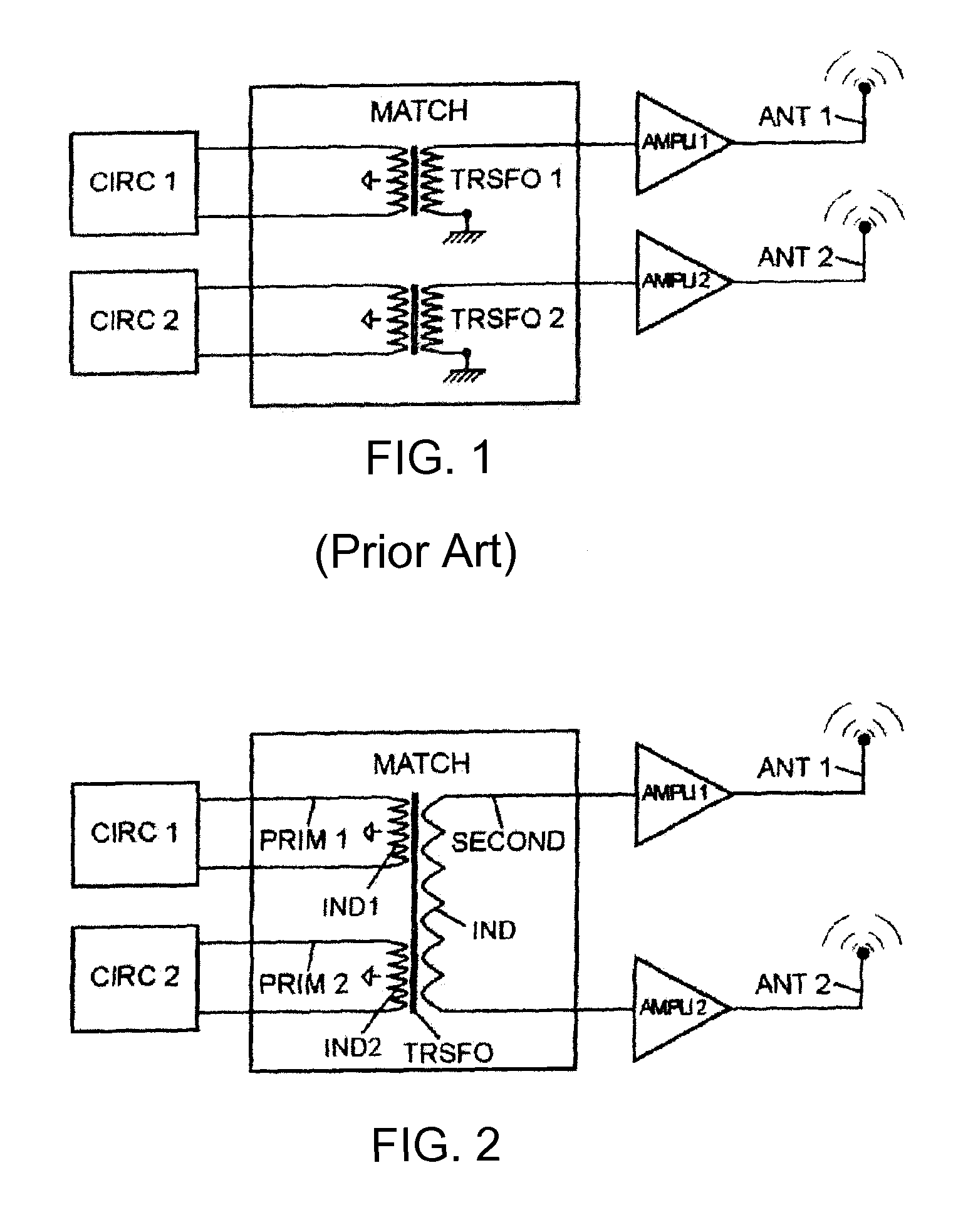
[0036]A radio frequency circuit according to one embodiment will now be described with reference to FIG. 2.

[0037]The structure in FIG. 2 reuses the elements CIRC1, CIRC2, AMPLI1, AMPLI2, ANT1, ANT2 of the circuit previously described with reference to FIG. 1.

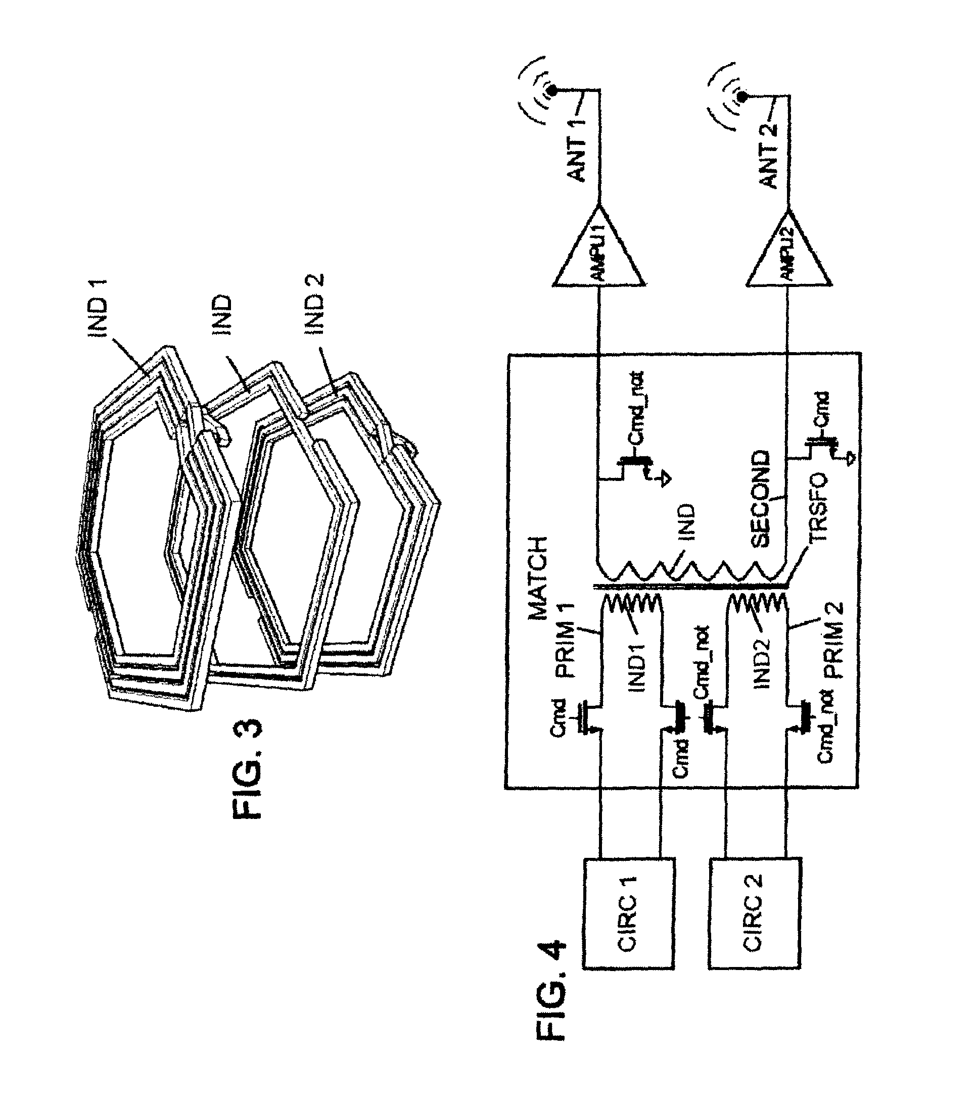
[0038]In the present embodiment, the matching circuit MATCH, positioned between the circuits CIRC1 and CIRC2 and the amplifiers AMPLI1 and AMPLI2, comprises a transformer TRSFO which has a secondary circuit SECOND comprising an inductor IND with one terminal connected to the first amplifier AMPLI1 and the other terminal connected to the second amplifier AMPLI2. In addition, the transformer comprises two primary circuits PRIM1 and PRIM2 magnetically coupled to the secondary circuit SECOND. The primary circuits PRIM1 and PRIM2 respectively comprise the inductors IND1 and IND2. The two output terminals of the circuit PRIM1 are connected to the terminals of the circuit CIRC1 and the two terminals of the circuit PRIM2 are connected t...


PUM

PropertyMeasurementUnit
radio frequencyaaaaaaaaaa
timeaaaaaaaaaa
electricallyaaaaaaaaaa

Abstract

The invention proposes a radio frequency circuit which comprises a transformer with a first primary circuit, a second primary circuit, and a secondary circuit, the secondary circuit comprising an integrated first inductor, this first inductor being positioned, on an axis orthogonal to a surface of the circuit, between an integrated second and third inductor respectively comprised in the first primary circuit and second primary circuit.

Description

TECHNICAL FIELD[0001]This invention relates to the transformers used in integrated electronic components.[0002]More particularly, it concerns the transformers used in radio frequency (RF) integrated circuits.TECHNOLOGICAL BACKGROUND[0003]In order to linearize radio transmissions, radio frequency transmitters and receivers use differential architectures. Antennas, as well as the power amplifiers associated with them, do not have this differential structure, however. A transformation of the differential signals from communication circuits should therefore be performed before they are delivered to the power amplification stage and the antenna (antenna stage, for short).[0004]The radio transmitters and receivers of today operate in different modes and on different frequency bands. In addition, transmitters and receivers currently have different outputs for various applications. For example, some devices can operate in compliance with different standards, and therefore have different ant...

Claims


Application Information

Patent Timeline
Patent Type & Authority Patents(United States)
IPC IPC(8): H03H7/38H01F19/04
CPCH01F19/04H03H7/38
Inventor CORDIER, CHRISTOPHEFRANCOIS, THOMASTESSON, OLIVIER
Owner ST ERICSSON SA
Features
  • R&D
  • Intellectual Property
  • Life Sciences
  • Materials
  • Tech Scout
  • Unparalleled Data Quality
  • Higher Quality Content
  • 60% Fewer Hallucinations
Learn More