Method and apparatus for directing steam distribution in a steam cooker

a technology of steam cooker and distribution method, which is applied in the direction of steam cooking vessel, milk treatment, kitchen equipment, etc., can solve the problems of difficult to achieve a high level of pan-to-pan uniformity within the cooking chamber, i.e., ensuring that each pan of food within the cooking chamber is heated substantially the same temperature, and may not reach the desired cooking temperature as quickly as other pans

Active Publication Date: 2015-06-30
ACCUTEMP PRODS
View PDF40 Cites 28 Cited by
  • Summary
  • Abstract
  • Description
  • Claims
  • Application Information

AI Technical Summary

Benefits of technology

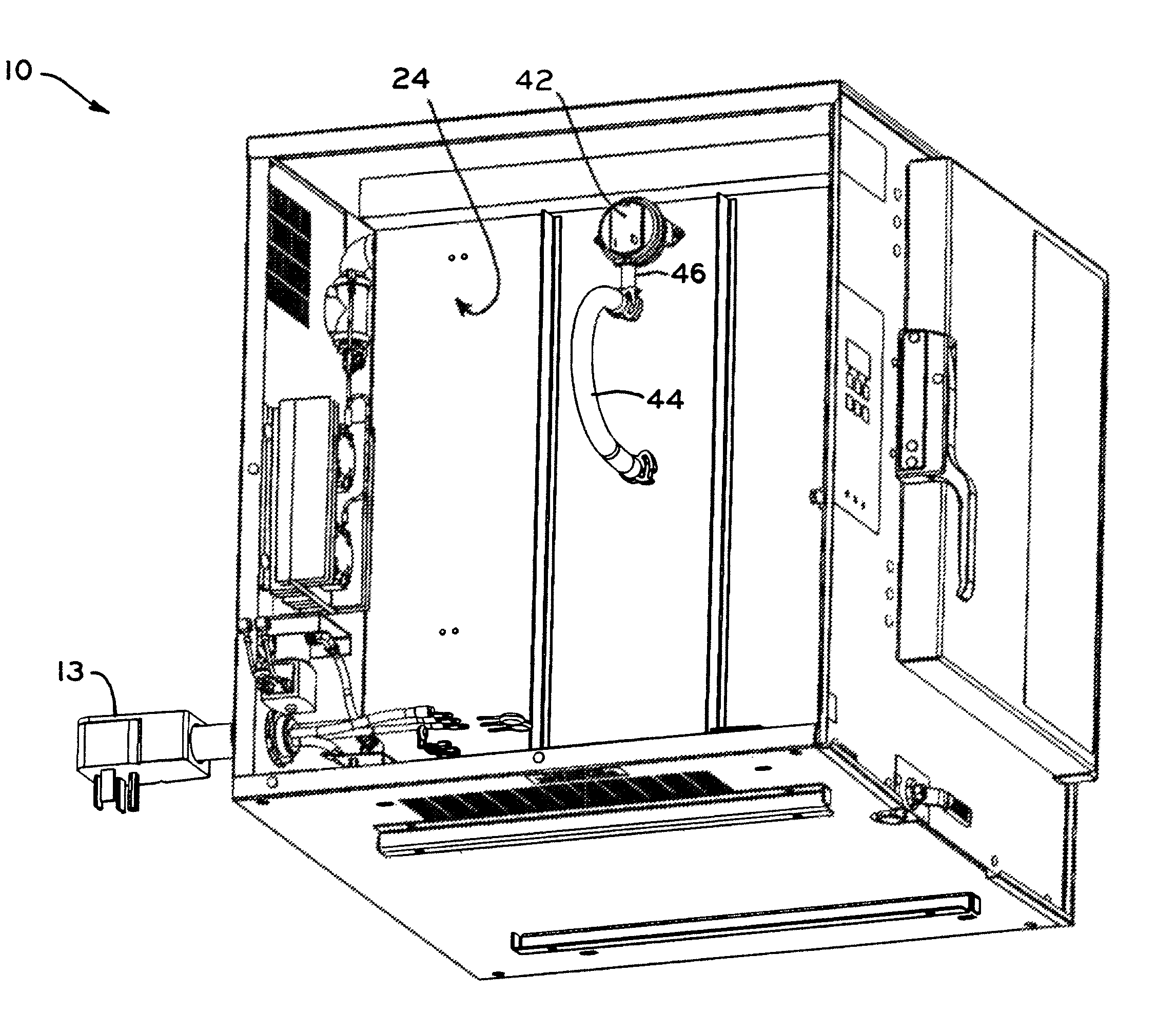
[0008]Advantageously, by selectively positioning the openings through the steam distributor, the steam distributor may allow for steam to exit into the cooking chamber at predetermined positions. As a result of the openings in the steam distributor, in conjunction with the formation of the plenum, steam may be distributed throughout the interior of the steam cooker in a manner that provides improved pan-to-pan uniformity, i.e., provides a more uniform cook temperature between each of the pans within the steam cooker, reduces cooking times, and allows the steam cooker to more quickly reach the desired cooking temperature. Further, by eliminating the need for a vacuum pump or other means to circulate steam within the cooking chamber of the steam cooker, the steam cooker generates substantially no noise during operation.
[0011]In a further form thereof, a steam cooker includes a cooking chamber defined by a plurality of walls; a quantity of water; a heater positioned in the steam cooker to heat the quantity of water, the heater generating steam from the quantity of water upon heating the water to a certain temperature; and a pressure switch having a pressure limit and in fluid communication with the cooking chamber via a pressure orifice formed in one of the plurality of walls of the cooking chamber, the pressure switch communicatively connected to the heater, the pressure switch positioned in an elevated position relative to the pressure orifice, the pressure switch measuring a pressure differential between the cooking chamber and an atmospheric pressure, the pressure switch operable to signal the heater to turn off when the differential is above the pressure limit. The elevated position of the pressure switch allows gravitational forces to draw any formed condensate back into the cooking chamber.
[0013]In one exemplary embodiment, the location, size, and number of openings in the steam distributor direct steam to each individual pan such as to achieve exceptional pan-to pan cooking uniformity.
[0014]In one exemplary embodiment, the steam distributor is adjacent to the long side of the food pans minimizing the length of the steam flow path across each pan.
[0019]In one exemplary embodiment, condensation in the pressure sensing device is prevented by a long length of tubing between the cooking and / or steam chamber and the pressure sensing device causing steam to condense in the tubing before it can reach the pressure sensing device and / or by keeping the pressure sensing device warm so as to prevent condensation in it.

Problems solved by technology

While prior art steam cooker designs are effective, achieving a high level of pan-to-pan uniformity within the cooking chamber, i.e., ensuring that each pan of food within the cooking chamber is heated to substantially the same temperature, may be difficult.
As a result, when the cooking chamber is loaded with pans of food that are to be cooked, some of the pans may not reach the desired cooking temperature as quickly as other pans.
In order to heat all of the pans to the desired cooking temperature, the pans that reach the cooking temperature first may have to be overheated, i.e., may have to be heated to a temperature in excess of the desired cooking temperature resulting in over cooked food.
Further, due to the constant operation of a mechanism to circulate the steam within the cooking chamber, a constant noise may be generated by the steam cooker.

Method used


Image

  • Method and apparatus for directing steam distribution in a steam cooker
  • Method and apparatus for directing steam distribution in a steam cooker
  • Method and apparatus for directing steam distribution in a steam cooker

Examples


example 1

Evaluation of Pan-to-Pan Uniformity

[0066]Ice melt tests were performed to evaluate the pan-to-pan uniformity of the steam cooker of the present design to three commercially available steam cookers: (1) a six pan Steam'N'Hold™ vacuum-capable connectionless steamer having a power input of 17 kW commercially available from AccuTemp Products, Inc., of Fort Wayne, Ind.; (2) a six pan Xtreme Steam™ connectionless steamer having a power input of 14 kW commercially available from Intek Manufacturing, LLC, of Fort Wayne, Ind.; and (3) a six pan Xtreme Steam™ connectionless steamer having a power input of 18 kW commercially available from Intek Manufacturing, LLC, of Fort Wayne, Ind. Steam'N'Hold and Xtreme Steam are a trademark of AccuTemp Products, Inc. of Fort Wayne, and Intek Manufacturing, LLC, of Fort Wayne, Ind., respectively.

[0067]The ice melt tests were performed in accordance with ASTM F1484-05, Standard Test Methods for Performance of Steam Cookers, available from ASTM Internationa...

example 2

Evaluation of the Cooking Productivity and Efficiency

[0071]A red potato cooking test was performed to evaluate the cooking productivity and efficiency of a steam cooker of the present design as compared to commercially available steam cookers. Specifically, a steam cooker of the present design was compared to the commercially available steam cookers identified above in Example 1.

[0072]Red potatoes are used to represent a food with a low surface area / volume ratio, which reduces condensation, decreases heat transfer, reduces productivity, and reduces cooking efficiency. The red potato test was performed in accordance with ASTM F1484-05, Standard Test Methods for Performance of Steam Cookers, available from ASTM International of West Conshohocken, Pa. Specifically, the red potato test uses a full load of pans, with each pan containing 8.0 lbs of red potatoes. The amount of time that it takes for the average potato temperature to reach 195° F. and the total energy used to achieve that a...

example 3

Single Serving Food Tests

[0074]In order to test the ability of a steam cooker of the present design to quickly heat single servings of food, a steam cooker of the present design was compared to a commercially available steam cooker, specifically, a six pan Steam'N'Hold™ vacuum-capable connectionless steamer having a power input of 17 kW commercially available from AccuTemp Products, Inc., of Fort Wayne, Ind.

[0075]Steam cookers are also commonly used to cook or warm small amounts, often single servings, of food. Many times a single serving is placed within a steam cooker and, before it is finished cooking, another serving is placed within the same steam cooker. In replicating this type of use, a small hole was drilled in one inch diameter nylon balls and a thermocouple was inserted into the hole so that the thermocouple extended into the center of the nylon ball. The nylon balls including the thermocouples were then placed in the center of three perforated hotel pans. The pans and ny...


PUM


Abstract

The present invention relates to a method and apparatus for directing steam distribution in a steam cooker. In one exemplary embodiment, steam is directed through a steam cooker by a plenum that is in fluid communication with a steam chamber. As steam is generated within the steam chamber, the steam fills the chamber where it is directed to the plenum. In one exemplary embodiment, the plenum is formed to extend vertically along an interior wall of the steam cooker. In one exemplary embodiment, the plenum is defined between an interior wall of the steam cooker and a steam distributor that has a plurality of openings formed therein. The openings in the steam distributor allow for steam rising within the plenum to exit into the cooking chamber by passing through the openings. A pressure switch may be utilized to turn off the steam generator in the steam cooker.

Description

CROSS REFERENCE TO RELATED APPLICATIONS[0001]This application claims the benefit under Title 35, U.S.C. §119(e) of U.S. Provisional Patent Application Ser. No. 61 / 145,598, entitled METHOD AND APPARATUS FOR DIRECTING STEAM DISTRIBUTION IN A STEAM COOKER, filed on Jan. 19, 2009, the disclosure of which is expressly incorporated by reference herein.BACKGROUND[0002]1. Field of the Invention[0003]The present invention relates to steam cookers.[0004]2. Description of the Related Art[0005]Steam cookers are used in commercial food service applications to quickly heat and / or cook food. In order to heat and / or cook food in a steam cooker, water is heated until it changes phase to become steam. The steam is then circulated through the cooker using a fan or other circulation mechanism to allow the steam to contact the food and increase the temperature of the food. Additionally, a vacuum pump may be used to remove air from the cooking chamber of the steam cooker. By removing air from the cooking...

Claims


Application Information

Patent Timeline
Patent Type & Authority Patents(United States)
IPC IPC(8): A47J27/04A21B3/04
CPCA21B3/04
Inventor SEITZ, CRAIG A.WOLF, LAWRENCE R.
Owner ACCUTEMP PRODS
Why Eureka
Try Eureka