
Rocket-propelled grenade

a rocket-propelled grenade and rocket-propelled technology, which is applied in the direction of ammunition projectiles, weapons, ammunition fuzes, etc., can solve the problems of inability to identify all participants, inability to provide sufficient light for effective use, and inability to temporarily visually impair opposing combatants or other unruly persons

Active Publication Date: 2015-06-30
LOCKHEED MARTIN CORP
View PDF88 Cites 15 Cited by
  • Summary
  • Abstract
  • Description
  • Claims
  • Application Information

AI Technical Summary

Benefits of technology

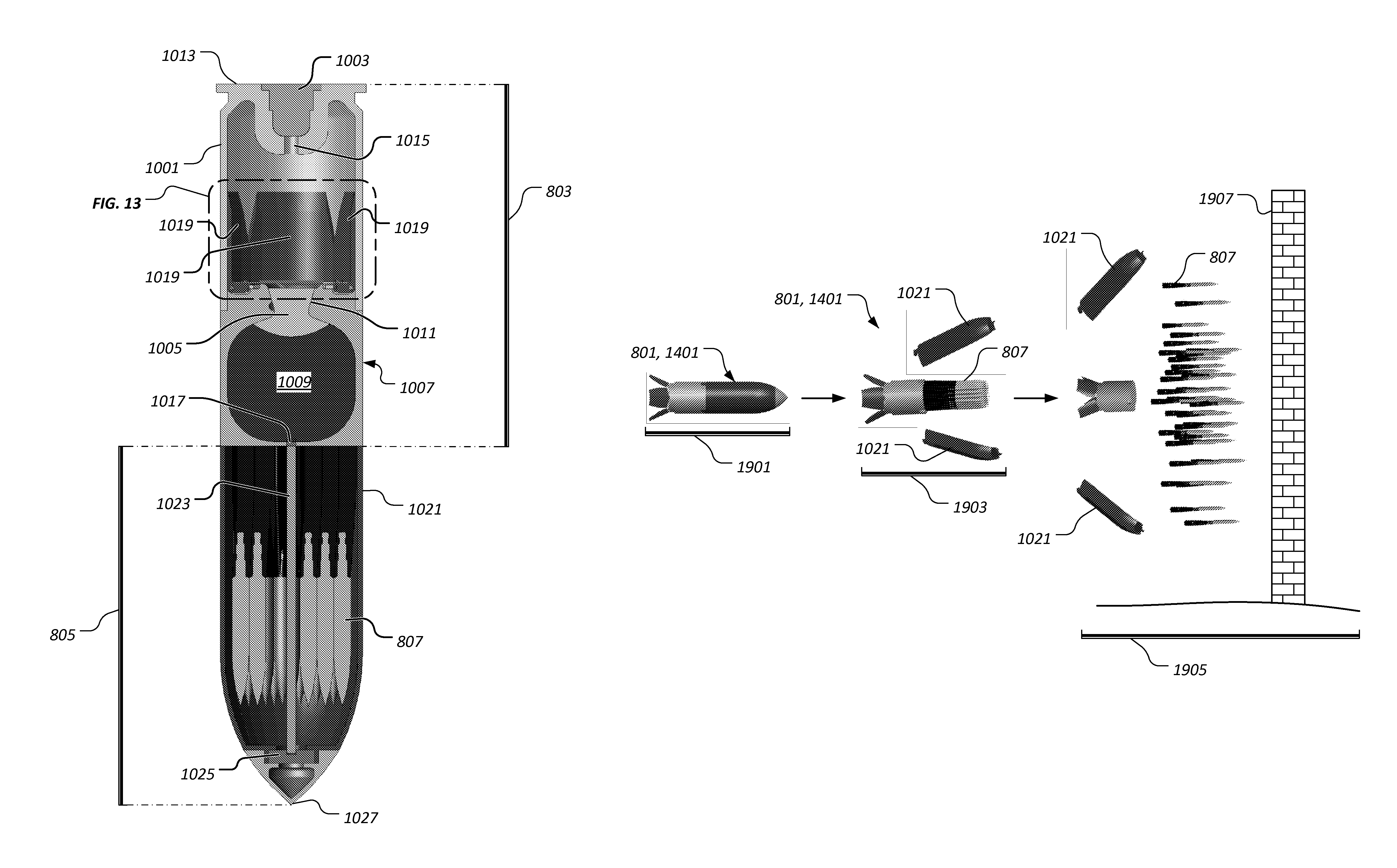
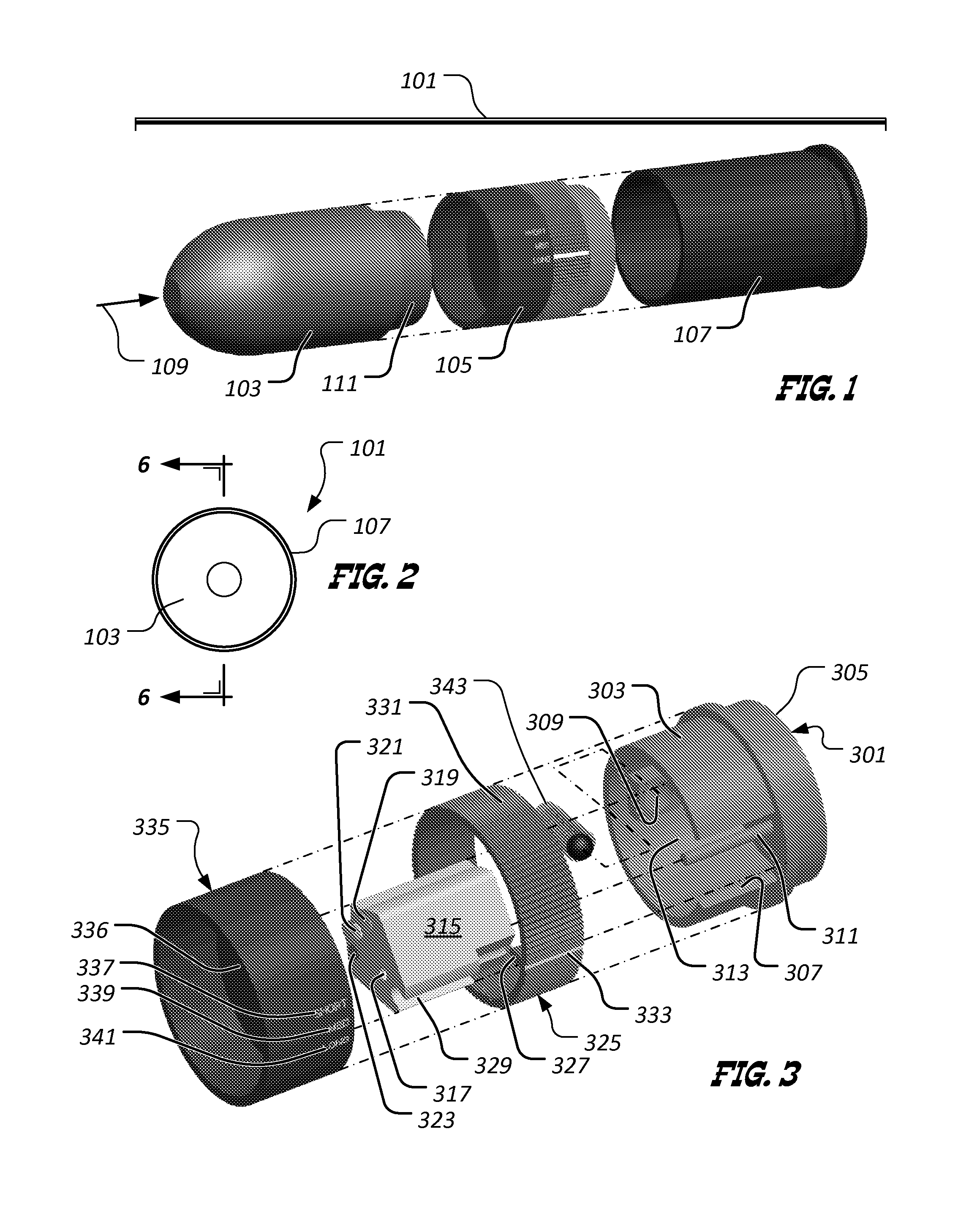
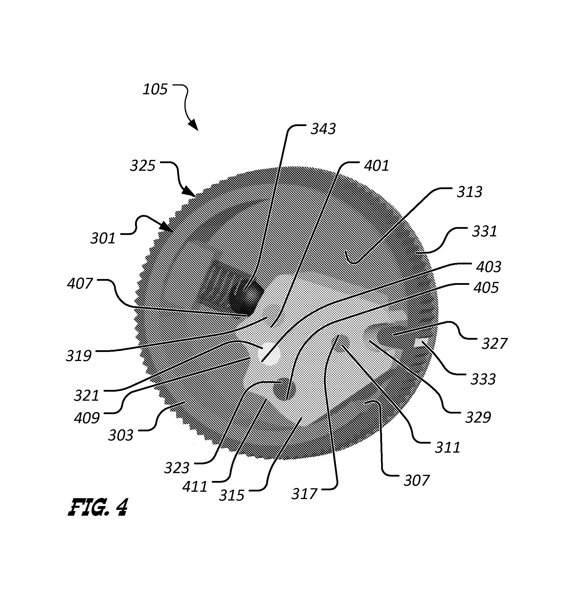
The present invention relates to rocket-propelled grenades and aims to address shortcomings in current technology. Specifically, the invention seeks to provide a solution for temporarily visually impairing opposing combatants or unruly persons in combat scenarios, as well as for breaching building walls in a safe and effective manner. The invention provides a novel feature in the form of a selectable fuzing section that can be used with rocket-propelled grenades to open a breach in a building wall and secure the building. The invention also includes various improvements to the design of the grenade, such as a more powerful fuzzing section and a more efficient payload section. Overall, the invention provides a more effective and safe solution for dealing with combat scenarios and protecting warfighters.

Problems solved by technology

One technique that is not available to current-day warfighters is to temporarily visually impair opposing combatants or other unruly persons.
Attempts have been made to utilize “star shells,” which fire a phosphorus-based flare into the air; however, such shells fail to provide light that is of sufficient intensity to be effective.
In military or police crowd control situations, and particularly in riot or violent confrontations involving large numbers of people, it is often desirable but impractical to identify all participants.
Members of such mobs will disperse unless physically restrained and current technology provides no way to easily identify a person at a later time that was involved in the confrontation or riot.
Failure to use such explosives properly can result in accidents that are lethal to nearby warfighters.
While anti-tank rockets can be effective, such rockets are expensive due to their particular characteristics.
Some such rockets can cost many thousands of dollars each and are, therefore, not cost effective for breaching walls.

Method used


Image

  • Rocket-propelled grenade
  • Rocket-propelled grenade
  • Rocket-propelled grenade

Examples


Embodiment Construction

[0026]Illustrative embodiments of the invention are described below. In the interest of clarity, not all features of an actual implementation are described in this specification. It will of course be appreciated that in the development of any such actual embodiment, numerous implementation-specific decisions must be made to achieve the developer's specific goals, such as compliance with system-related and business-related constraints, which will vary from one implementation to another. Moreover, it will be appreciated that such a development effort might be complex and time-consuming but would nevertheless be a routine undertaking for those of ordinary skill in the art having the benefit of this disclosure.

[0027]Reference will now be made in detail to the present exemplary embodiments of the invention, examples of which are illustrated in the accompanying drawings.

[0028]FIG. 1 depicts a partially exploded, perspective view of a first illustrative embodiment of a rocket-propelled gre...


PUM


Abstract

A rocket-propelled grenade includes a payload section, a selectable fuzing section joined to the payload section, and a propulsion section joined to the selectable fuzing section. A rocket-propelled grenade includes a propulsion section and a payload section operably associated with the propulsion section. The payload section includes a shell, one or more penetrators disposed in the shell, and a charge for compromising the shell to deploy the one or more penetrators when the charge is initiated.

Description

CROSS-REFERENCE TO RELATED APPLICATIONS[0001]This application claims the benefit of U.S. Provisional Patent Application No. 61 / 256,258; filed 29 Oct. 2009; and entitled “Grenade,” which is hereby expressly incorporated herein by reference for all purposes.BACKGROUND[0002]1. Field of the Invention[0003]The present invention relates generally to rocket-propelled grenades.[0004]2. Description of Related Art[0005]Modern urban warfare presents warfighters with many different combat scenarios. For example, it is generally desirable and often more effective to use non-lethal means to control opposing combatants. One technique that is not available to current-day warfighters is to temporarily visually impair opposing combatants or other unruly persons. Attempts have been made to utilize “star shells,” which fire a phosphorus-based flare into the air; however, such shells fail to provide light that is of sufficient intensity to be effective.[0006]In military or police crowd control situation...

Claims


Application Information

Patent Timeline
IPC IPC(8): F42B12/56F42B10/02F42B10/30F42B12/02F42B12/46F42B15/10F42C14/00
CPCF42B15/10F42B12/46F42C14/00F42B12/02F42B10/02F42B10/30F42B10/14F42B12/06F42B12/42F42C19/02
Inventor THOMAS, TOBY D.GREEN, RICHARD L.RECORD, JONATHAN H.STRAUCH, ROBBIE S.HUNN, DAVID L.
Owner LOCKHEED MARTIN CORP
Learn More