Unlock instant, AI-driven research and patent intelligence for your innovation.

Composite sensor for detecting angular velocity and acceleration

a sensor and angular velocity technology, applied in the field of composite sensors, can solve the problem of bulkyness of the composite sensor for detecting angular velocity and acceleration

Active Publication Date: 2015-06-30
PANASONIC INTELLECTUAL PROPERTY MANAGEMENT CO LTD
View PDF41 Cites 1 Cited by
  • Summary
  • Abstract
  • Description
  • Claims
  • Application Information

AI Technical Summary

Benefits of technology

The downsized sensor effectively processes angular velocity and acceleration signals without the bulk of a circuit board, enhancing its suitability for compact applications in aircraft and vehicle navigation systems.

Problems solved by technology

The composite sensor for detecting angular velocity and acceleration is thus bulky.

Method used


Image

  • Composite sensor for detecting angular velocity and acceleration
  • Composite sensor for detecting angular velocity and acceleration
  • Composite sensor for detecting angular velocity and acceleration

Examples


Embodiment Construction

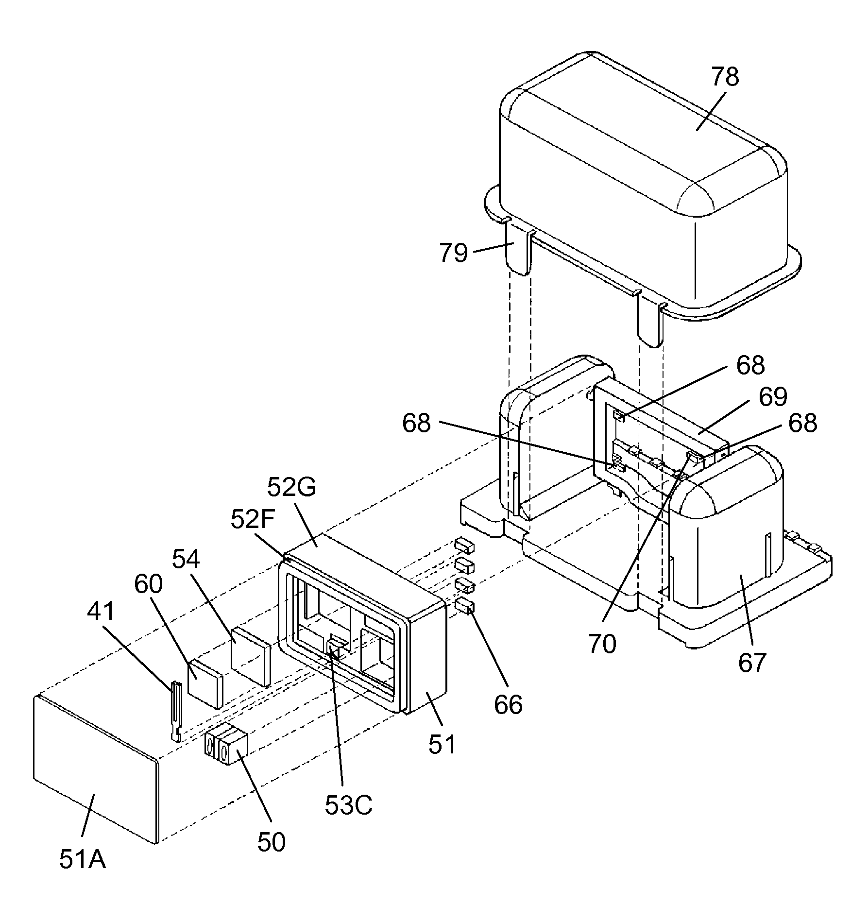
[0034]FIG. 1 and FIG. 2 are an exploded perspective view and a perspective view of a composite sensor for detecting angular velocity and acceleration in accordance with an embodiment of the present invention. FIG. 3 is a perspective view of an angular velocity detecting element of the composite sensor for detecting angular velocity and acceleration. FIG. 4 is a sectional view of a first arm section of the angular velocity detecting element. FIG. 5 is a lateral sectional view of the vicinity around an angular velocity signal processing IC and an acceleration signal processing IC placed in a housing of the composite sensor. FIG. 6 is a bottom view of the housing. The composite sensor has angular velocity detecting element 41, acceleration detecting element 50, angular velocity signal processing IC 54, acceleration signal processing IC 60, housing 51, capacitor 66, compartment 67, mounting section 69, and cover 78.

[0035]As shown in FIG. 3, angular velocity detecting element 41 shaped l...


PUM


Abstract

A composite sensor for detecting angular velocity and acceleration includes an angular velocity detecting element, an acceleration detecting element, an angular velocity signal processing IC, an acceleration signal processing IC, and a housing. The housing is formed of a multilayered circuit board and accommodates the angular velocity detecting element, the acceleration detecting element, the angular velocity signal processing IC, and the acceleration signal processing IC. The housing connects the angular velocity detecting element electrically to the angular velocity signal processing IC, and also connects the acceleration detecting element electrically to the acceleration signal processing IC.

Description

[0001]This application is a U.S. National Phase Application of PCT International Application PCT / JP2008 / 002765.TECHNICAL FIELD[0002]The present invention relates to a composite sensor to be used for posture control or navigation systems of movable bodies such as aircrafts and vehicles.BACKGROUND ART[0003]A conventional composite sensor for detecting angular velocity and acceleration is configured as shown in FIGS. 8 to 11. FIGS. 8 and 9 show an exploded perspective view and a lateral sectional view of the conventional composite sensor for detecting angular velocity and acceleration. FIG. 10 shows a perspective view of an angular velocity detecting element of the conventional composite sensor for detecting angular velocity and acceleration. FIG. 11 shows a perspective view of the conventional composite sensor for detecting angular velocity and acceleration. This composite sensor includes angular velocity detecting unit 1, acceleration detecting unit 11, circuit board 15, shield case ...

Claims


Application Information

Patent Timeline
Patent Type & Authority Patents(United States)
IPC IPC(8): G08B21/00G01P15/18G01C19/5607G01P1/02G01C19/56G01C19/5628G01P15/00
CPCG01P1/023G01C19/5607G01P15/18H01L2224/16225H01L2224/32145H01L2224/48465H01L2224/73265H01L2224/0557H01L2224/05573H01L2924/00014H01L2224/04042H01L2224/05571H01L2224/0554H01L2224/05599H01L2224/0555H01L2224/0556G01C21/10G01P1/02G01P3/00G01P15/00
Inventor OHKOSHI, HIDEO
Owner PANASONIC INTELLECTUAL PROPERTY MANAGEMENT CO LTD