Space shuttle orbiter and return system

a space shuttle and orbiter technology, applied in the field of space systems, can solve the problems of fuel and/or structural inefficiency of space launch systems, inability to adapt to the weight and size of payload modules, and high cost of structures

Active Publication Date: 2015-07-07
BIOSPHERE AEROSPACE
View PDF26 Cites 5 Cited by
  • Summary
  • Abstract
  • Description
  • Claims
  • Application Information

AI Technical Summary

Benefits of technology

[0005]It is understood that the principles underlying the basic configuration of the orbiter may also have other applications in which it is desired to have a vehicle that permits the ability to reuse certain components while at the same time permitting for the disposal of components that are relatively inexpensive compared to the reused components.

Problems solved by technology

One significant shortcoming associated with known space launch systems is that they typically have fixed structures and are therefore incapable of being adapted to the weight and size of the payload module that they are transporting.
Because space launch systems typically transport one or more payload modules that have varying weight and / or sizes, the space launch systems are oftentimes fuel and / or structurally inefficient.
Inherent in such designs, however, are higher structural weight and design considerations which make such structures expensive.
Additionally, because such systems include a significant amount of dead weight, which must be transported back after the payload is released, they have high fuel requirements which translate to significant additional system costs.

Method used


Image

  • Space shuttle orbiter and return system
  • Space shuttle orbiter and return system
  • Space shuttle orbiter and return system

Examples


Embodiment Construction

[0066]Specific, non-limiting embodiments of the present invention will now be described with reference to the drawings. It should be understood that such embodiments are by way of example only and merely illustrative of but a small number of embodiments within the scope of the present invention. Various changes and modifications obvious to one skilled in the art to which the present invention pertains are deemed to be within the spirit, scope and contemplation of the present invention as further defined in the appended claims.

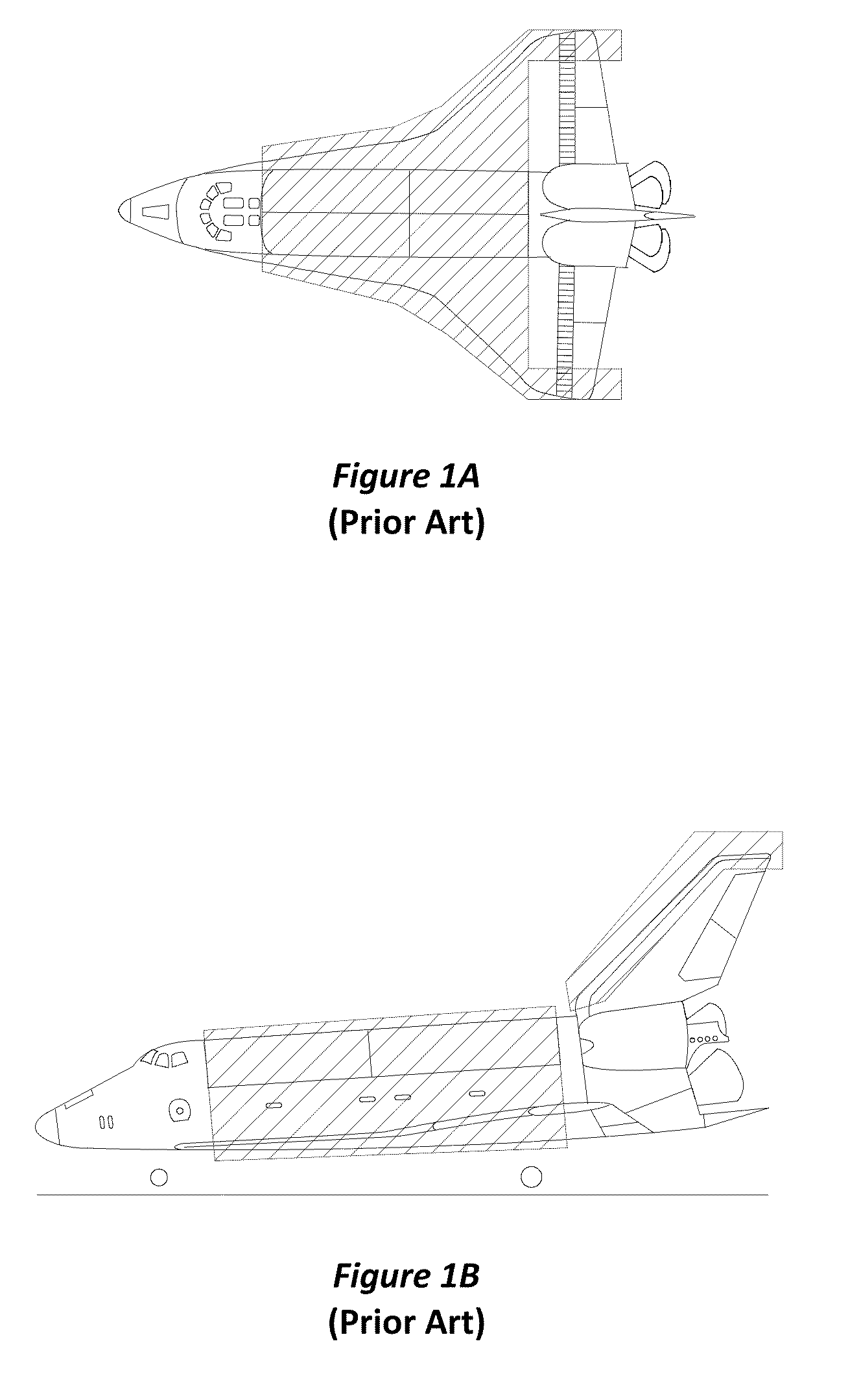
[0067]FIGS. 1A and 1B are top and side views, respectively, of a known space shuttle configuration that may be used to deliver a payload module into orbit. The space shuttle orbiter described herein is designed to eliminate a significant portion of the dead weight represented in the shaded portions of the space shuttle and also to provide a degree of adaptability of the orbiter structure based on the weight and size of a particular payload module. The shaded po...


PUM


Abstract

A launch system comprises a nose section comprising a nose coupling surface, a tail section comprising a tail coupling surface facing the nose coupling surface and a mast coupling the nose and tail sections. The mast is configured to expand and retract to displace the nose and tail sections within a range of distances from one another. In a retracted state, the nose and tail sections are either structurally coupled to one another at the nose and tail coupling surfaces or structurally coupled to at least one integrated module located between the nose and the tail sections.

Description

FIELD OF THE INVENTION[0001]The present invention relates generally to space systems and, more particularly, to a space shuttle orbiter or rocket that is configured to deliver a payload module, or assist in delivering a payload module, and to return with the relatively expensive components of the orbiter or rocket.BACKGROUND[0002]Space launch systems have long been used to transfer payload modules into orbit and beyond. One significant shortcoming associated with known space launch systems is that they typically have fixed structures and are therefore incapable of being adapted to the weight and size of the payload module that they are transporting. Because space launch systems typically transport one or more payload modules that have varying weight and / or sizes, the space launch systems are oftentimes fuel and / or structurally inefficient.[0003]There have been continuing efforts at making the entire launch system reusable. Inherent in such designs, however, are higher structural wei...

Claims


Application Information

Patent Timeline
Patent Type & Authority Patents(United States)
IPC IPC(8): B64G1/00B64G1/14B64G1/40B64G1/58B64G1/22
CPCB64G1/14B64G1/002B64G1/22B64G1/222B64G1/40B64G1/401B64G1/403B64G1/58B64G1/62B64G1/223B64G1/005
Inventor HELOU, JR., ELIE
Owner BIOSPHERE AEROSPACE
Why Eureka
Try Eureka