Display device

a display screen and display technology, applied in non-linear optics, instruments, optics, etc., can solve the problems of reducing the light reflection efficiency, and affecting the effect of so as to reduce the light reflection efficiency and the effect of reducing the brightness of the display screen

Active Publication Date: 2015-07-07
FUNAI ELECTRIC CO LTD
View PDF5 Cites 0 Cited by
  • Summary
  • Abstract
  • Description
  • Claims
  • Application Information

AI Technical Summary

Benefits of technology

[0007]However, with the directly backlit device (e.g., the display device) disclosed in Patent Literature 1, slits are formed at the corners of the sheet body (e.g., the reflective sheet) (at the boundaries between the four side face parts). Thus, it has been discovered that even when the sheet body is folded so that the end edges of adjacent side face parts contact via the slits, gaps tend to occur at these contact portions (at the boundary between two side face parts). Therefore, it has been discovered that light from the light source tends to leak through the gaps at the corners of the sheet body, and the gaps at the corners of the sheet body can widen until the overall shape of the sheet body is lost, which decreases the light reflection efficiency and lowers the brightness of the display screen.
[0008]One aspect is to provide a display device with which there is less decrease in the brightness of a display screen.

Problems solved by technology

Thus, it has been discovered that even when the sheet body is folded so that the end edges of adjacent side face parts contact via the slits, gaps tend to occur at these contact portions (at the boundary between two side face parts).
Therefore, it has been discovered that light from the light source tends to leak through the gaps at the corners of the sheet body, and the gaps at the corners of the sheet body can widen until the overall shape of the sheet body is lost, which decreases the light reflection efficiency and lowers the brightness of the display screen.

Method used


Image

  • Display device
  • Display device
  • Display device

Examples


Embodiment Construction

[0020]A selected embodiment will now be explained with reference to the drawings. It will be apparent to those skilled in the field from this disclosure that the following descriptions of the embodiment are provided for illustration only and not for the purpose of limiting the invention as defined by the appended claims and their equivalents.

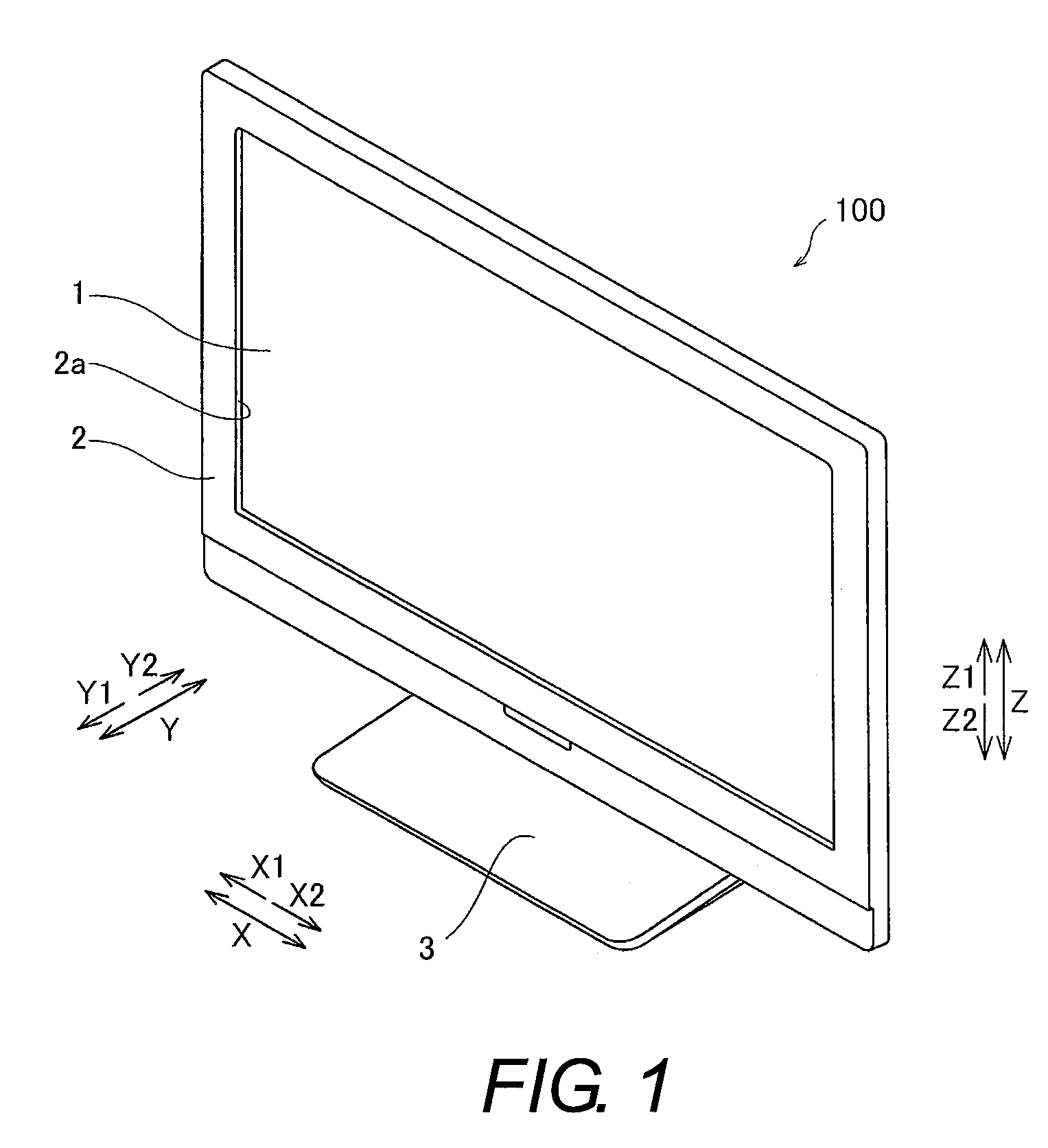
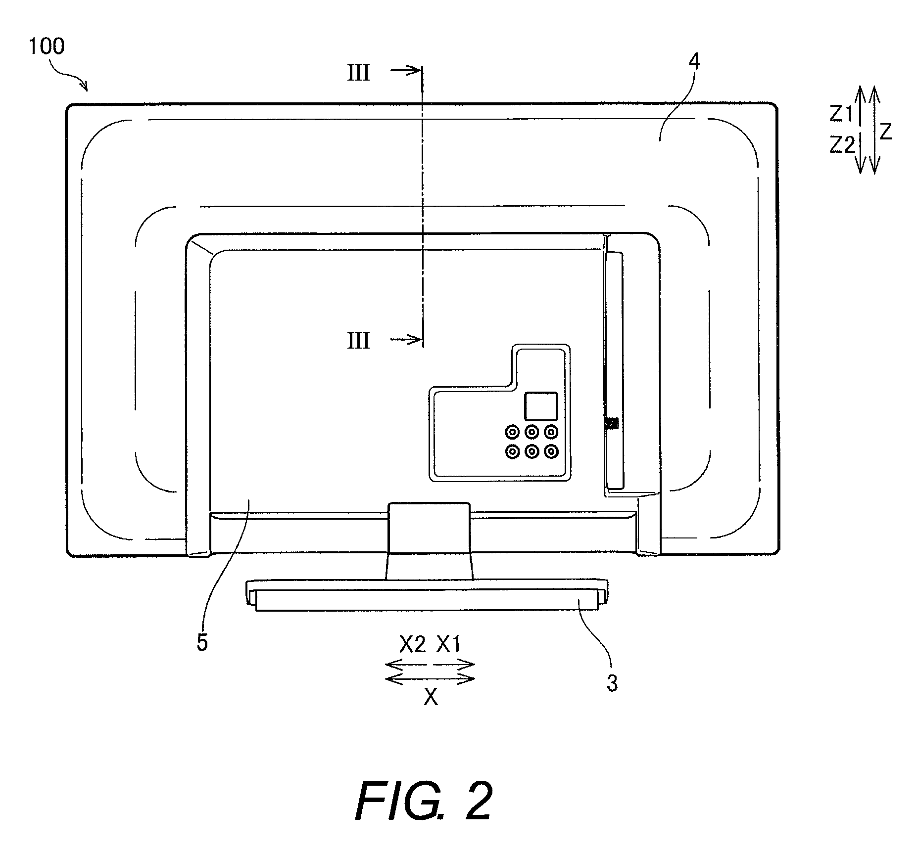
[0021]Referring to FIGS. 1 to 8, a liquid crystal television set 100 is illustrated in accordance with one embodiment. The liquid crystal television set 100 is an example of the “display device” of the present invention. In the illustrated embodiment, while the liquid crystal television set 100 is illustrated as an example of the display device, it will be apparent to those skilled in the art from this disclosure that the present invention can be applied to different types of display devices.

[0022]As shown in FIGS. 1 and 2, the liquid crystal television set 100 includes a display component 1, a front housing 2, and a stand member 3. The display ...


PUM

PropertyMeasurementUnit
dimensionaaaaaaaaaa
shapeaaaaaaaaaa
light reflection efficiencyaaaaaaaaaa

Abstract

A display device includes a display component, a light source, a rear side support member, and a reflective sheet. The light source is disposed on a rear side of the display device relative to the display component. The reflective sheet includes a bottom face part, a first side face part and a second side face part. The first and second side face parts have first and second protrusions at adjacent end edge portions of the first and second side face parts, respectively. The first protrusion overlaps with the end edge portion of the second side face part from the rear side while the reflective sheet is attached to the rear side support member. The second protrusion overlaps with the end edge portion of the first side face part from the rear side while the reflective sheet is attached to the rear side support member.

Description

CROSS-REFERENCE TO RELATED APPLICATIONS[0001]This application claims priority to Japanese Patent Application No. 2013-020218 filed on Feb. 5, 2013. The entire disclosure of Japanese Patent Application No. 2013-020218 is hereby incorporated herein by reference.BACKGROUND[0002]1. Field of the Invention[0003]This invention generally relates to a display device. More specifically, the present invention relates to a display device having a reflective sheet for reflecting light from a light source towards a display component.[0004]2. Background Information[0005]Generally, a display device having a reflective sheet for reflecting light from a light source towards a display component is known (see Japanese Unexamined Patent Application Publication No. 2010-49846 (Patent Literature 1), for example).[0006]The above-mentioned Patent Literature 1 discloses a directly backlight device (display device) having a concave (rectangular in plan view) sheet body (e.g., a reflective sheet) that reflects...

Claims


Application Information

Patent Timeline
Patent Type & Authority Patents(United States)
IPC IPC(8): G02F1/1335
CPCG02F1/1336G02F1/133605G02F1/133611
Inventor TANABE, NORITAKA
Owner FUNAI ELECTRIC CO LTD
Why Eureka
Try Eureka