Molding flask for a molding machine and a molding process using the molding flask

a molding machine and mold technology, applied in the direction of moulding machines, drying machines, moulding machines, etc., can solve the problems of difficult to achieve the accuracy of overlapping, mold shift, and unsatisfactory gap between

Active Publication Date: 2015-07-21
SINTOKOGIO LTD
View PDF16 Cites 1 Cited by
  • Summary
  • Abstract
  • Description
  • Claims
  • Application Information

AI Technical Summary

Benefits of technology

[0005]Accordingly, one object of the present invention is to provide a flask that prevents a mold from shifting and a mold from dropping. The present invention also provides a molding process using the flask.
[0016]The flaskless molding machine that can use the method of the present invention preferably includes a rotation frame for moving the flask unit between a position where the defining step is carried out and a position where the introducing step is carried out, and a pair of driving means for driving the pair of pressing members, respectively. In this case, the driving means may be moved with the rotation frame in unison. Alternatively, the driving means may be in a fixed position. In the latter case, the rigidity of the rotation frame can be minimized. Alternatively, one of the pair of the driving means is moved with the rotation frame in unison, while the other driving means is in a fixed position. In this case, the rigidity of the rotation frame can be reduced.

Problems solved by technology

For this reason, an undesirable gap can appear between the upper flask and the lower flask at the side that is opposed to the connecting side when they are caused to overlap, while a gap can appear therebetween at the connecting side when a pattern is drawn.
This results in that the face of the mold cannot be disposed in parallel with the mating face of the flask, and thus this causes a mold shift.
The mold shift prevents the mold from being vertically drawn from a pattern and thus causes problems such as a mold dropping.
Although the upper flask and the lower flask with a mold therein overlap by especially using any aligning device for the mold, indeed, accuracy for the overlapping can be difficult to achieve.

Method used


Image

  • Molding flask for a molding machine and a molding process using the molding flask
  • Molding flask for a molding machine and a molding process using the molding flask
  • Molding flask for a molding machine and a molding process using the molding flask

Examples


Embodiment Construction

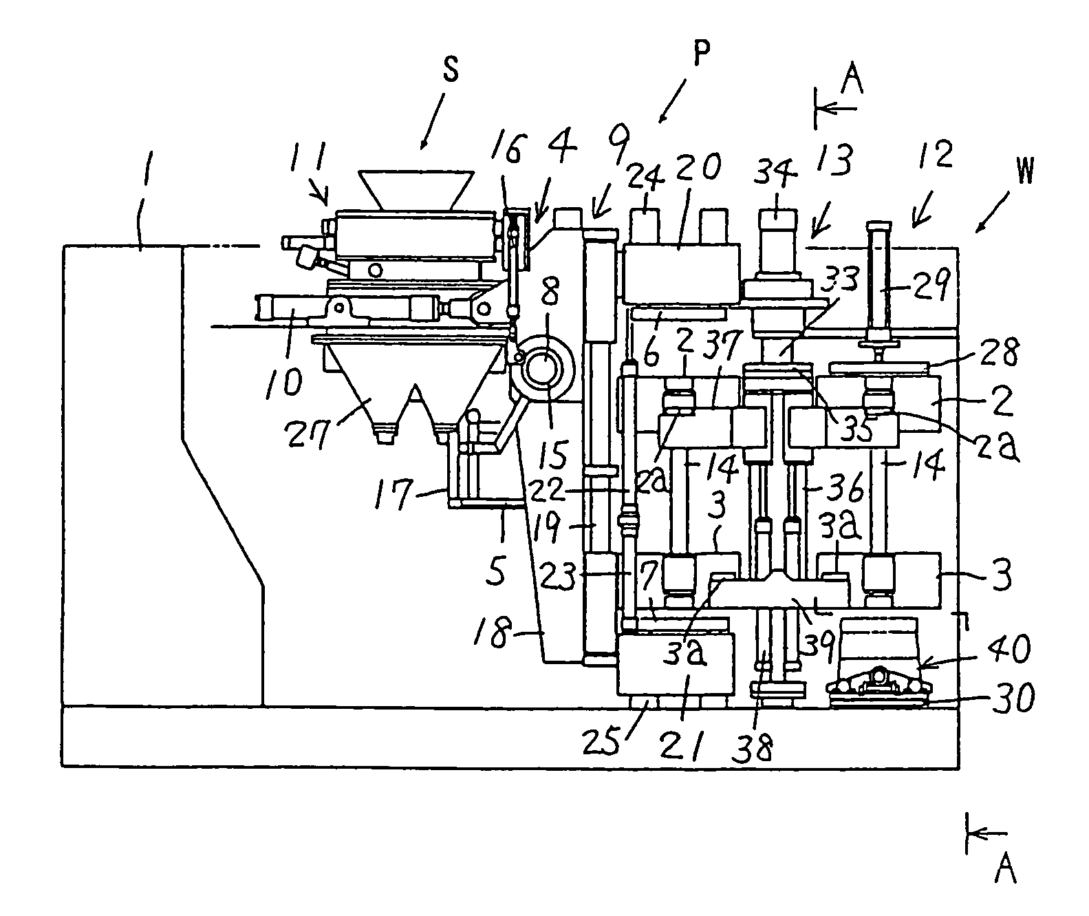
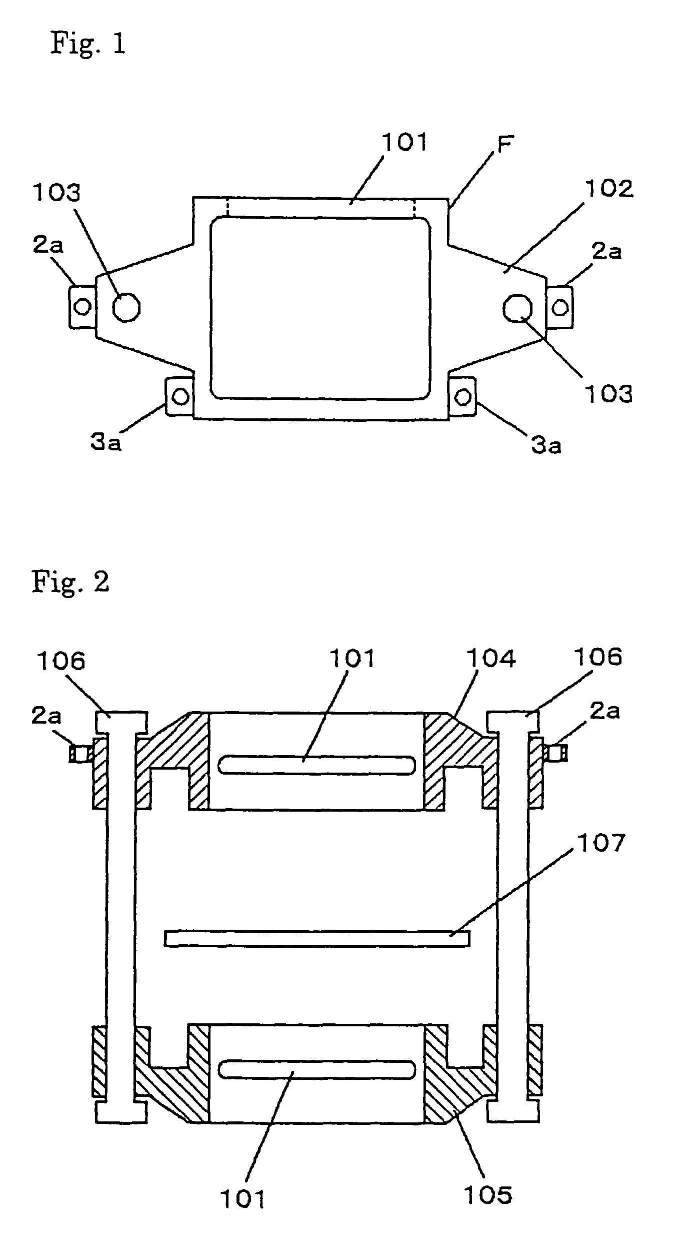
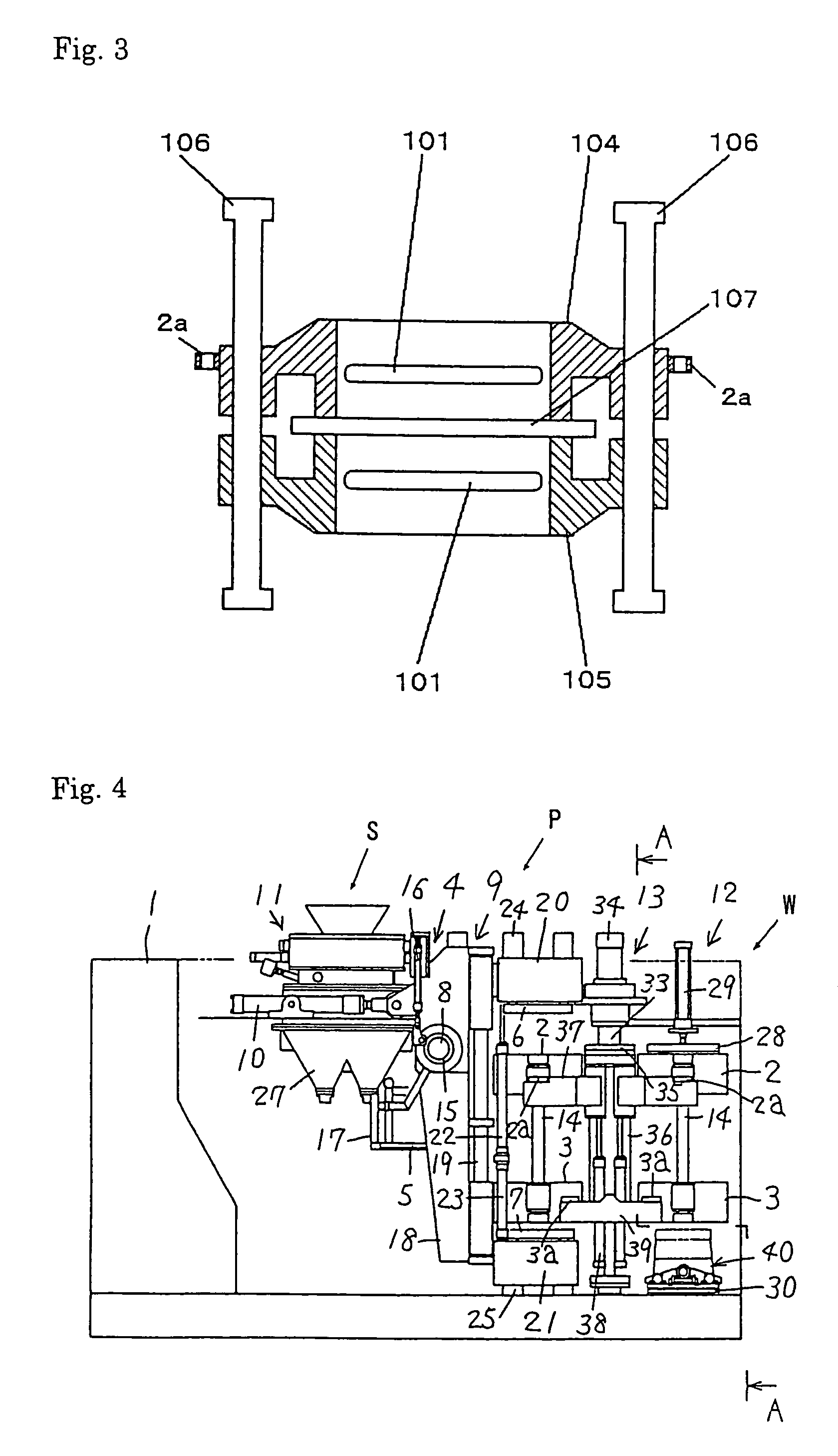
[0047]FIG. 1 shows a flask F of the present invention. In FIG. 1, two flasks F are caused to overlap. The upper flask F is provided with engaging members 2a, while the lower flask F is provided with engaging members 3a. The other arrangements of the upper flask are the same as those of the lower flask.

[0048]Each flask F includes integral peripheral walls (or a body) that define an opening. One side of the peripheral walls has at least one inlet 101 for introducing molding sand into the opening.

[0049]Flanges (mounting members) 102 are attached to the outer surfaces of a pair of opposed walls of the peripheral walls of the flask F. One through bore is bored through each flange 102 such that two bores are opposed to each other across the opening of the flask.

[0050]The flanges 102 may be integrally molded to the body of the flask F. Alternatively, the flanges 102 may be separately manufactured from the body such that they can be mechanically attached to the body. For example, the flask ...


PUM

PropertyMeasurementUnit
forceaaaaaaaaaa
forcesaaaaaaaaaa
molding spacesaaaaaaaaaa

Abstract

A flask for containing mold sand within it prevents any mold shifting or mold dropping. Each of an upper flask 2 and a lower flask 3 includes a body that defines an opening in which a sand mold is to be molded. The body has at least one inlet 101 for introducing the mold sand into the opening. Two flanges 102 are extended from the body such that they are opposed to each other across the opening. Each flange has a through bore. The flask also includes engaging members for engaging an actuator in the outside of the flask such that a force or forces from said actuator could be transmitted to the flask. An upper flask 104 and a lower flask 105 are opposed to each other across a pattern plate 107. They are integrally assembled to make a flask unit by means of a pair of connecting rods 106 that are fitted in each bore.

Description

FIELD OF THE INVENTION[0001]This invention relates to a flask of a molding machine for molding a mold with molding sand, and a method for molding a mold using the invented flask.BACKGROUND OF THE INVENTION[0002]Flaskless molding machines are known as disclosed in such as Japanese Patent Early-Publication No. 7-16705, filed Jul. 2, 1993, assigned to the present applicant. The flaskless molding machines employ a flaskless molding process, where a molded mold is removed from a pair of flasks (an upper flask and a lower flask), and its sides are covered by mold jackets, if needed, such that it is then poured.[0003]In the conventional flasks of the molding machine, as shown in the above publication, the paired upper and lower flasks are cantilevered supported such that they are connected to each other at just one of their sides. For this reason, an undesirable gap can appear between the upper flask and the lower flask at the side that is opposed to the connecting side when they are cause...

Claims


Application Information

Patent Timeline
Patent Type & Authority Patents(United States)
IPC IPC(8): B22C11/10B02C17/16B09B3/00C02F1/38F26B17/10F26B17/24B22C15/02B22C21/00F26B5/00B22C15/08B22C21/10B22C15/06B22C15/24B22C15/28B01D21/06B01D21/24B01D21/26B01F5/10B01F7/16B01F7/18B01F7/28B01F13/10B01F15/00B02C17/00B01F27/94C02F1/00C02F103/08
CPCF26B5/00B01D21/06B01D21/245B01D21/2444B01D21/26B01F5/104B01F7/1625B01F7/18B01F7/285B01F13/1011B01F13/1041B01F15/00974B01F15/00987B02C17/007B02C17/16B02C17/163B09B3/00B22C11/10B22C15/02B22C15/06B22C15/08B22C15/24B22C15/28B22C21/10C02F1/38F26B17/107F26B17/24B01D21/267B01F2215/005B01F2215/0014B01F2215/0032B01F2215/0481C02F2103/08C02F2301/024C02F2301/026B22C7/04B22C21/12B01F25/52B01F27/81B01F27/941B01F33/8052B01F33/83B01F27/90B01F35/188B01F35/187B01F2101/06B01F2101/22B01F2101/30
Inventor HIRATA, MINORU
Owner SINTOKOGIO LTD
Why Eureka
Try Eureka