Formwork support beam

a technology of support beams and structural members, applied in the direction of girders, joists, trusses, etc., can solve the problems of heavy beams, adverse weather conditions, and structural members that are subject to significant mechanical stresses, and achieve improved mechanical properties, improved durability, and improved mechanical properties

Inactive Publication Date: 2015-08-11
ULMA C Y E
View PDF9 Cites 2 Cited by
  • Summary
  • Abstract
  • Description
  • Claims
  • Application Information

AI Technical Summary

Benefits of technology

[0010]There is obtained as a result a formwork structural member that as well as meeting the mechanical requirements demanded of this type of formwork structural member, which are set out in the respective standards, has a weight optimised for its application as a formwork support, improved mechanical properties and better behaviour in the event of it receiving impacts than that offered by conventional formwork structural members mainly made of wood.
[0011]In addition, the formwork structural member offers increased durability, as the metal casing ensures the formwork structural member behaves well in conditions of use and storage in the event that it may receive impacts etc, and in particular in the weather conditions to which the structural member is subjected during its lifetime. In addition, the formwork structural member obtained can be repaired in a simple manner, increasing its durability.

Problems solved by technology

These types of structural members are subjected to significant mechanical stresses, in particular to high static charges and impacts caused by hits, collisions, etc., which affect the ends of the beams in particular.
Furthermore, as they are used outside, they are subjected to adverse weather conditions.
There are known structural members made of metal, preferably steel, which as well as meeting mechanical requirements are resistant to adverse meteorological conditions, but which also have very heavy beams and are thus very expensive.
As a result, the material most commonly used for these types of structural members is wood, with which a beam that is low in weight is achieved and which meets mechanical requirements, although said beam is less durable, as it is a material that suffers, among other things, adverse weather conditions.
In addition, the metal web is substantially hollow, the drawback of which is that concrete may get inside it, limiting its repeated use.

Method used


Image

  • Formwork support beam
  • Formwork support beam
  • Formwork support beam

Examples


Embodiment Construction

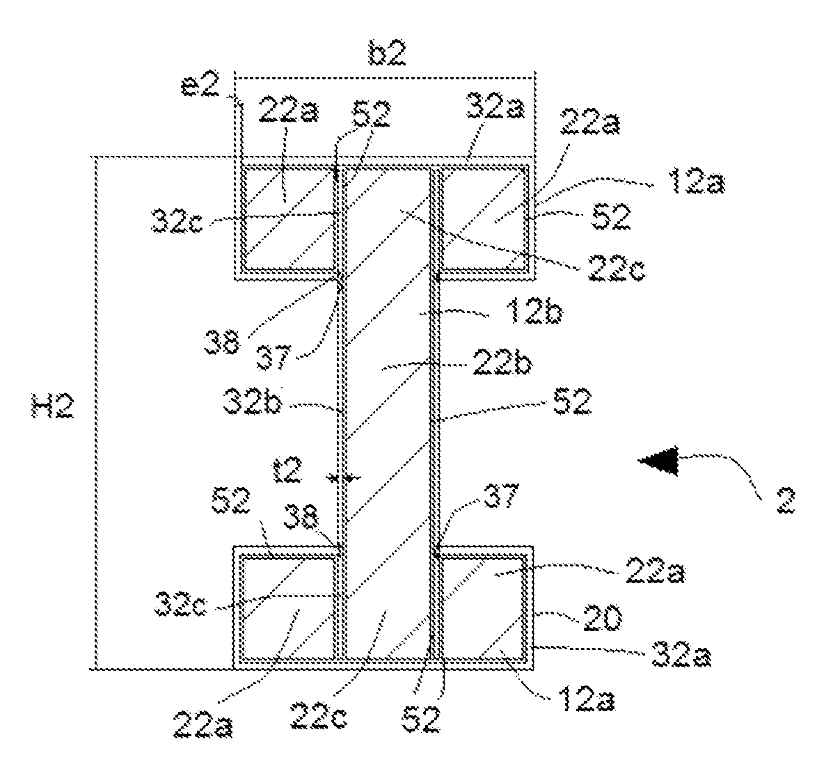
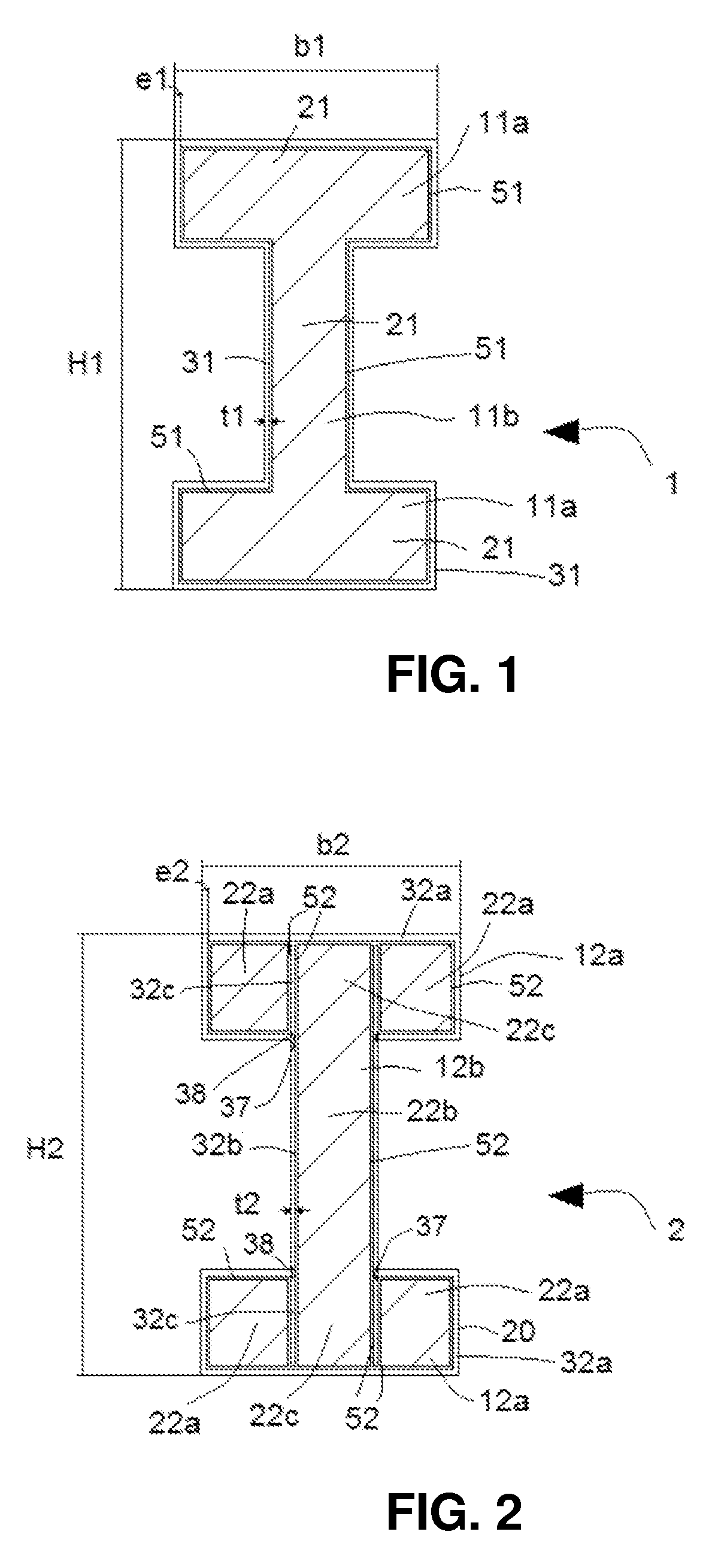
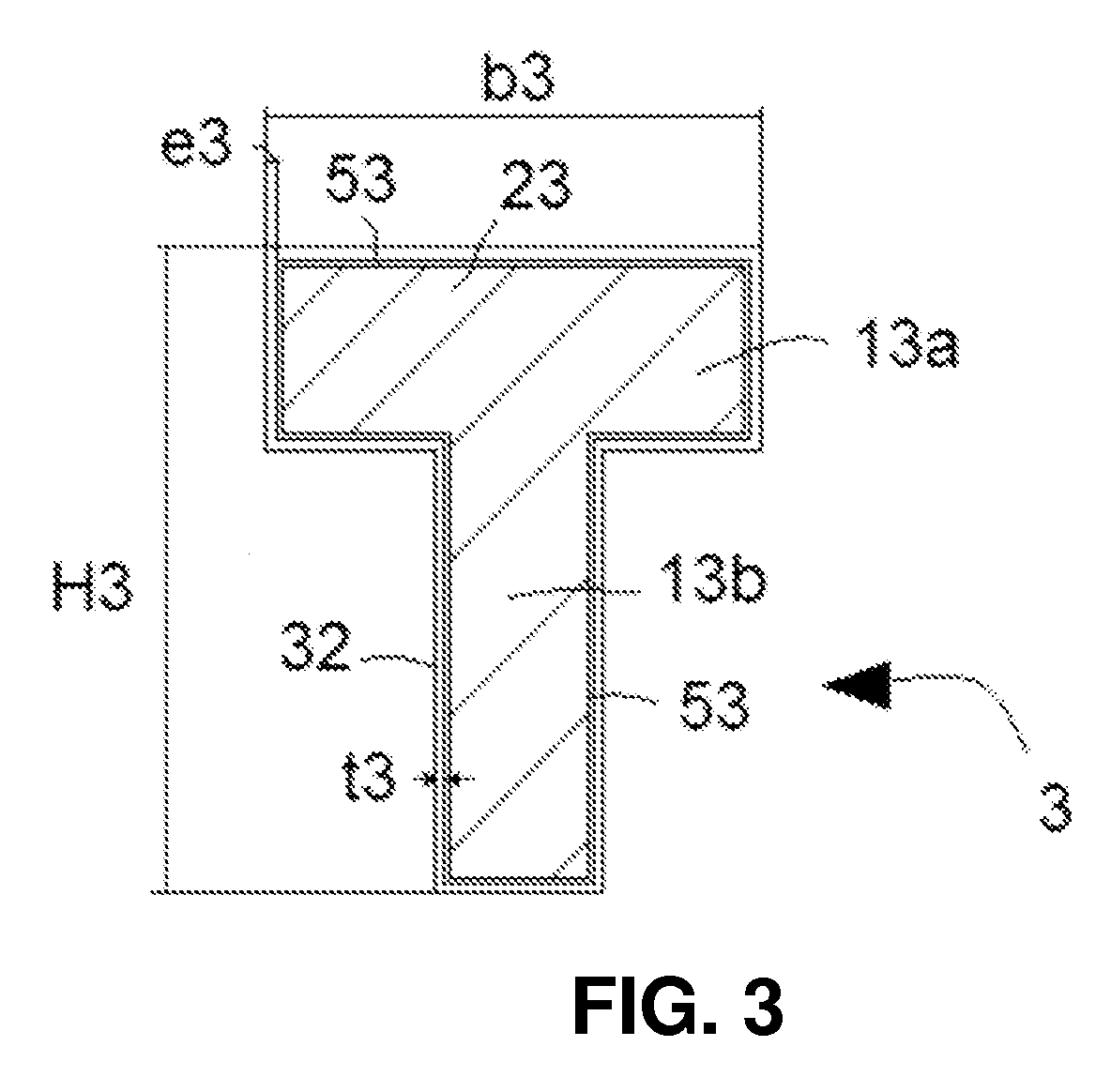
[0019]The formwork structural member 1;2;3;5 shown in FIGS. 1 to 5, according to the invention, meets the mechanical requirements demanded of formwork support beams.

[0020]In the embodiments shown in FIGS. 1,2 and 4, the formwork structural member 1;2;5 has a section substantially or an I or double T shape, comprising a web 11b;12b;15b and two flanges 11a;12a;15a each one of which extends continuously from an end of the corresponding web 11b;12b;15b. The mechanical and dimensional requirements of these formwork structural members are set out in the EN13377:2002 standard. The formwork structural member 1;2;5 is thus defined by a height H1;H2;H5 that is between approximately 160 mm and approximately 240 mm, and a width b1;b2;b5 of the respective flange 11a;12a;15a between approximately 65 mm and approximately 80 mm. In addition, the formwork structural member 1;2;5 supports, depending on the height dimension H1;H2;H5 and the width b1;b2;b5 of the respective flange 11a;12a;15a, a flexur...


PUM


Abstract

A formwork structural member having at least one core made of a material that has a density between approximately 40 kg / m3 and approximately 500 kg / m3, and at least one metal casing that substantially covers an outer contour of the core, the metal casing being arranged attached to the core.

Description

CROSS-REFERENCE TO RELATED APPLICATIONS[0001]This application relates to and claims the benefit and priority to International Application No. PCT / EP2012 / 062617, filed Jun. 28, 2012, which claims the benefit and priority to Spanish Patent Application No. 201131127, filed Jul. 1, 2011.TECHNICAL FIELD[0002]This invention relates to a formwork structural member.BACKGROUND[0003]There are known structural members such as beams, used in the construction industry, in particular to support formworks. These types of structural members are subjected to significant mechanical stresses, in particular to high static charges and impacts caused by hits, collisions, etc., which affect the ends of the beams in particular.[0004]The structural members used to support a formwork preferably have an I or double T cross-section, comprising two flanges connected to each other through a web that may be solid or a truss. These structural members are designed to support, generally, a flexural rigidity (E) betw...

Claims


Application Information

Patent Timeline
Patent Type & Authority Patents(United States)
IPC IPC(8): E04G11/50E04C3/29E04C3/04
CPCE04C3/29E04G11/50E04C3/291E04C2003/0413E04C2003/0421E04C2003/0439E04C2003/0452
Inventor CALVO ECHEVESTE, IBONLECETA LASA, JON INAKIFABIAN MARIEZCURRENA, AITORRUIZ DE AZUA VAQUERO, ALEXANDERCORTES MARTINEZ, FERNANDO
Owner ULMA C Y E
Why Eureka
Try Eureka