Bow

a technology of bows and arrows, applied in the field of bows, can solve problems such as the degradation of achieve the effect of improving the accuracy of arrows and quick absorption of vibration

Inactive Publication Date: 2015-08-11
WIN & WIN
View PDF33 Cites 13 Cited by
  • Summary
  • Abstract
  • Description
  • Claims
  • Application Information

AI Technical Summary

Benefits of technology

[0005]To solve the above conventional problems or defects, it is an object of the present invention to provide a bow that attenuates vibration generated from one end portion of each of wings coupled to both end portions of a handle and simultaneously absorbs the vibration rapidly, thereby improving accuracy of an arrow.
[0006]To accomplish the above and other objects of the present invention, according to an aspect of the present invention, there is provided a bow comprising: a handle at a central portion of which a grip portion is formed in which the grip portion is gripped by a user; a pair of wings that are respectively coupled to both ends of the handle; and a bow string that is tied between the pair of the wings, wherein a coupling pin is formed in one side of a rear side of one end of each wing coupled to the handle, and a fitting groove is formed at one end of each wing, wherein a coupling groove into which the coupling pin of each wing is coupled is formed at one end of the handle to which each wing is coupled, and a fixing pin that is inserted into the fitting groove of each wing to support one end of each wing is formed at the one end of the handle to which each wing is coupled, and wherein a buffer pin member that is configured to include a pin member that is inserted into an insertion hole formed in each wing and coupled to the handle and a first cushioning member that is formed between a front end of the pin member and each wing, is provided at each end of the handle to which each wing is coupled, to thereby attenuate vibration generated at the one end of each wing coupled to the handle when using the bow, to thus improve accuracy of an arrow.
[0010]According to another aspect of the present invention, there is also provided a bow comprising: a handle at a central portion of which a grip portion is formed in which the grip portion is gripped by a user; a pair of wings that are respectively coupled to both ends of the handle; and a bow string that is tied between the pair of the wings, wherein a coupling pin is formed in a rear side of one end of each wing coupled to one end of the handle, and a fitting groove is formed at one end of each wing, wherein a coupling groove into which the coupling pin of each wing is inserted is formed at one end of the handle to which each wing is coupled, and a fixing pin that is inserted into the fitting groove of each wing is formed at the one end of the handle to which each wing is coupled, and wherein a buffer pin member that is configured to include a pin member that is inserted into an insertion hole formed in the handle and is coupled to one end of each wing and a cushioning member that is formed between a rear end of the pin member and the handle, is provided at each end of the handle to which each wing is coupled, to thereby attenuate vibration generated at the one end of each wing coupled to the handle when using the bow, to thus improve accuracy of an arrow.
[0012]According to still another aspect of the present invention, there is also provided a bow comprising: a handle at a central portion of which a grip portion is formed in which the grip portion is gripped by a user; a pair of wings that are respectively coupled to both ends of the handle; and a bow string that is tied between the pair of the wings, wherein a coupling pin is formed in one side of a rear side of one end of each wing coupled to one end of the handle, and a fitting groove is formed at one end of each wing, wherein a coupling groove into which the coupling pin of each wing is inserted is formed at one end of the handle to which each wing is coupled, and a fixing pin that is inserted into the fitting groove of each wing is formed at the one end of the handle to which each wing is coupled, and wherein a front support portion that is located in front of one end of each wing is formed at each end of the handle to which each wing is coupled, and a cushioning member is provided between the front support portion and each wing, to thereby attenuate vibration generated at the one end of each wing coupled to the handle when using the bow, to thus improve accuracy of an arrow.
[0014]According to yet another aspect of the present invention, there is also provided a bow comprising: a handle at a central portion of which a grip portion is formed in which the grip portion is gripped by a user; a pair of wings that are respectively coupled to both ends of the handle; and a bow string that is tied between the pair of the wings, wherein a coupling pin is formed in one side of a rear side of one end of each wing coupled to one end of the handle, and a fitting groove is formed at one end of each wing, wherein a coupling groove into which the coupling pin of each wing is inserted is formed at one end of the handle to which each wing is coupled, and a fixing pin that is inserted into the fitting groove of each wing is formed at the one end of the handle to which each wing is coupled, and wherein a buffer pin member that is configured to include a pin member that is formed between both sides of the handle that is positioned at both sides of each wing and that is disposed in front of each wing, and a cushioning member that surrounds the outer circumferential surface of the pin member is provided at one end of the handle to which one end of each wing is coupled, to thereby attenuate vibration generated at the one end of each wing coupled to the handle when using the bow, to thus improve accuracy of an arrow.
[0015]As described above, the bow according to the present invention suppresses displacement at one end of each wing coupled to the handle, and simultaneously attenuates vibration generated at the one end of each wing, to also rapidly absorb the vibration and to thereby provide an effect of improving accuracy of an arrow.

Problems solved by technology

This displacement may occur and be finally transferred to the handle 10, together with vibration generated by the wings during firing of an arrow, to thereby cause degradation of accuracy of the arrow.

Method used


Image

  • Bow
  • Bow
  • Bow

Examples


first embodiment

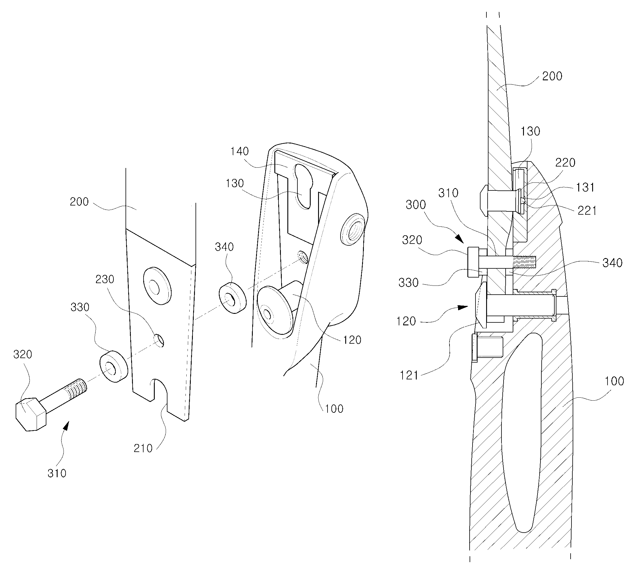
[0027]As illustrated, the bow according to the present invention includes: an elongated handle 100 extending in a generally longitudinal direction and having a pair of longitudinally opposite end and a central portion between the opposite ends of the handle 100; a pair of wings 200 that extend in the generally longitudinal direction and are respectively coupled to the longitudinally opposite ends of the handle 100; and a bow string that is tied between the pair of the wings 200. A grip portion 11, best shown in FIG. 1, is formed at the central portion of the elongated handle 100. The grip portion 11 is adapted to be gripped by a user. Here, a coupling pin 220 is formed in a rear side of one end of each wing 200 coupled to the handle 100, and a fitting groove 210 is formed at one end of each wing 200. In addition, a coupling groove 130 into which the coupling pin 220 of each wing 200 is coupled is formed at one end of the handle 100 to which each wing 200 is coupled, and a fixing pin...

third embodiment

[0042]A buffer pin member 500 in the third embodiment includes a pin member 510 that is inserted into an insertion hole 150 of the handle 100 and coupled to each wing 200, and a first cushioning member 530 that is formed between a rear end 520 of the pin member 510 and the handle 100.

[0043]In the third embodiment, the pin member 510 of the buffer pin member 500 is inserted into the insertion hole 150 of the handle 100 at the rear side of the handle 100, to then be coupled to each wing 200, and a rear end 520 of the pin member 510 is disposed at the rear side of the handle 100. The pin member 510 is detachably screwed with each wing 200 between the coupling groove 130 and the fixing pin 120.

[0044]A first cushioning member 530 is coupled to the pin member 510 between the rear end 520 of the pin member 510 and the handle 100, and the material of the first cushioning member 530 is made in the same manner as that of the first embodiment.

[0045]In the third embodiment, when the pin member ...

fourth embodiment

[0048]In the fourth embodiment, instead of the buffer pin member in the previous embodiments, a front support portion 170 is formed at one end of the handle 100 coupled to each wing 200 and a cushioning member 600 is provided between the front supporting portion 170 and each wing 200.

[0049]In this embodiment, the front support portion 170 is bent in an L-shaped form at both sides 160 of the handle 100 that is located at both sides of each wing 200, and is located in front of each wing 200. In addition, the front support portion 170 is formed to have a predetermined length in the longitudinal direction. In addition, the cushioning member 600 having the same length as that of the front support portion 170 is combined between the front support portion 170 and each wing 200 on the rear surface of the front supporting portion 170. The material of the cushioning member 600 is the same as those of the previous embodiments.

[0050]Thus, even in the fourth embodiment, a configuration such as t...


PUM


Abstract

Provided is bow including: a handle; a pair of wings; and a bow string, wherein a coupling pin is formed in a rear side of one end of each wing coupled to the handle, and a fitting groove is formed at one end of each wing, wherein a coupling groove into which the coupling pin of each wing is coupled is formed at one end of the handle, and a fixing pin that is inserted into the fitting groove of each wing is formed at the one end of the handle, and wherein a buffer pin member that is configured to include a pin member that is inserted into an insertion hole formed in each wing and coupled to the handle and a first cushioning member that is formed between a front end of the pin member and each wing, is provided at each end of the handle.

Description

CROSS-REFERENCE TO RELATED APPLICATION AND CLAIM TO PRIORITY[0001]This application claims the benefit of Korean Patent Application No. 10-2013-0064817, filed on Jun. 5, 2013, in the Korean Intellectual Property Office, the disclosure of which is incorporated herein by reference.FIELD OF THE INVENTION[0002]The present invention relates to a bow, and more particularly, to a bow that attenuates vibration generated at the ends of wings coupled to a handle when using the bow, to thus improve accuracy of an arrow.BACKGROUND OF THE INVENTION[0003]As shown in FIG. 1, a bow that is currently being used is configured to include: a handle 10 at a central portion of which a grip portion 11 is formed in which the grip portion 11 is gripped by a user; a pair of wings 20 that are respectively coupled to both ends of the handle 10; and a bow string 30 that is tied between the wings 20. Further, as shown in FIG. 2, the handle 10 is combined with each wing 20 in which a fixing pin 12 formed in the ha...

Claims


Application Information

Patent Timeline
Patent Type & Authority Patents(United States)
IPC IPC(8): F41B5/00F41B5/14F41B5/20F41B5/10
CPCF41B5/0026F41B5/0052F41B5/0031F41B5/10F41B5/1426
Inventor PARK, DONG WONYOU, JAE SEONYI, CHANG HO
Owner WIN & WIN
Why Eureka
Try Eureka