Fast knockdown cutting tool assembly

a cutting tool and fast technology, applied in the field of cutting tools, can solve the problems of time-consuming and inconvenient installation or uninstallation of cutting tools, no management system between the conventional holding device and cutting tools, and it is difficult to avoid unauthorized or improper assembly of cutting tools with the tool machine. , to achieve the effect of quick installation or uninstallation

Inactive Publication Date: 2015-08-18
GISON MASCH CO LTD
View PDF7 Cites 15 Cited by
  • Summary
  • Abstract
  • Description
  • Claims
  • Application Information

AI Technical Summary

Benefits of technology

[0008]It is therefore a primary object of the present invention to provide a cutting tool assembly in which the cutting tool can be quickly installed or uninstalled.
[0009]It is a further object of the present invention to provide the above fast knockdown cutting tool assembly, which includes a mandrel member and a cutting tool. Only a mandrel member and a cutting tool with identical specific combination code can be truly assembled and connected.
[0019]According to the above arrangement, the cutting tool can be quickly and conveniently plugged into the mandrel member and locked therewith. The position and depth of the alignment sink must conform to the position and length of the alignment pin for truly connecting the cutting tool with the mandrel member. With the specific conformation, the mandrel member and the cutting tool can be truly assembled and connected. Therefore, a user can manage the cutting tools to avoid incorrect installation or unauthorized installation of the cutting tools.

Problems solved by technology

Therefore, it is time-consuming and inconvenient to install or uninstall the cutting tool.
Moreover, there is no management system between the conventional holding device and cutting tool.
Therefore, it is hard to avoid unauthorized or improper assembly of the cutting tool with the tool machine.

Method used


Image

  • Fast knockdown cutting tool assembly
  • Fast knockdown cutting tool assembly
  • Fast knockdown cutting tool assembly

Examples


Embodiment Construction

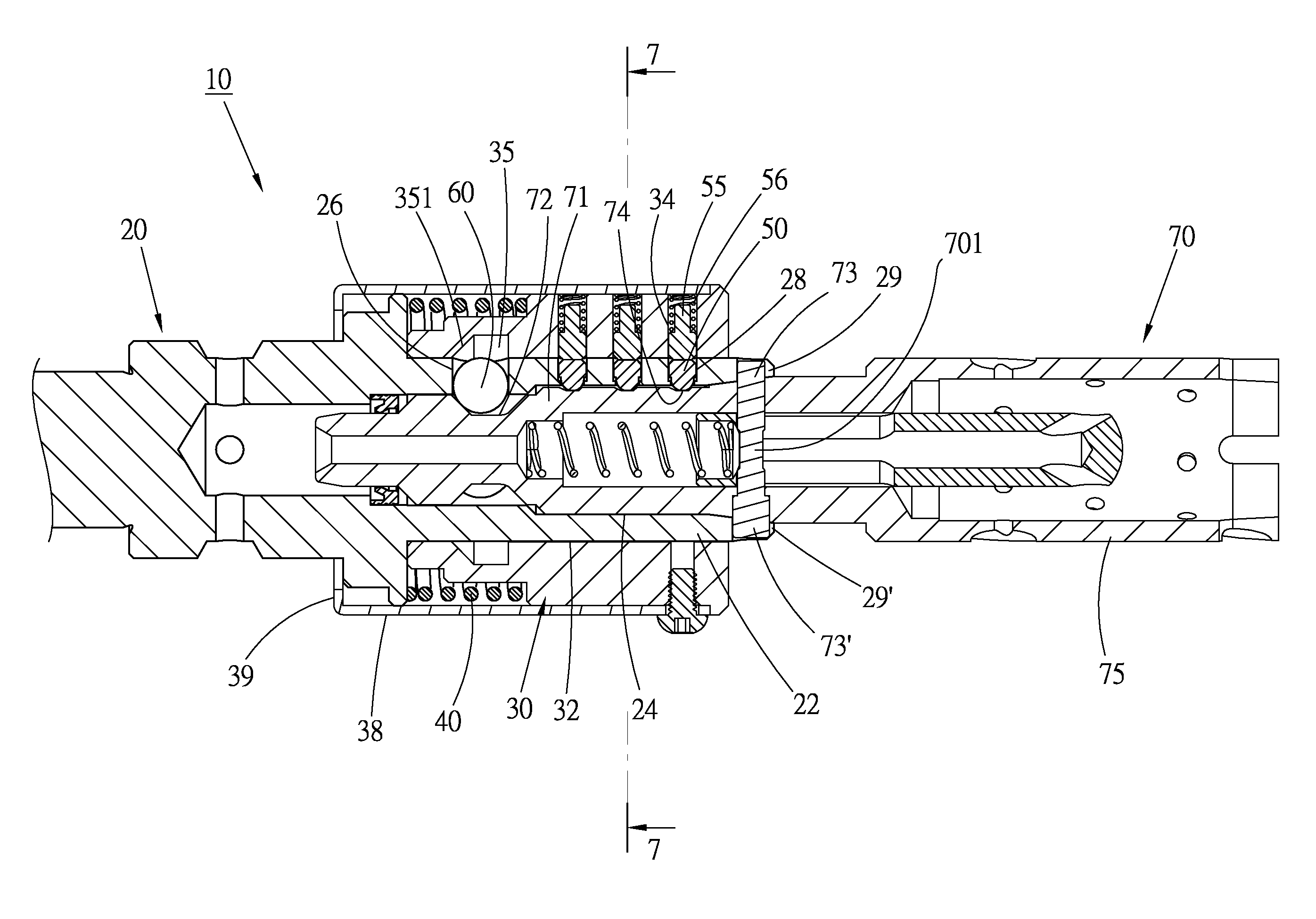
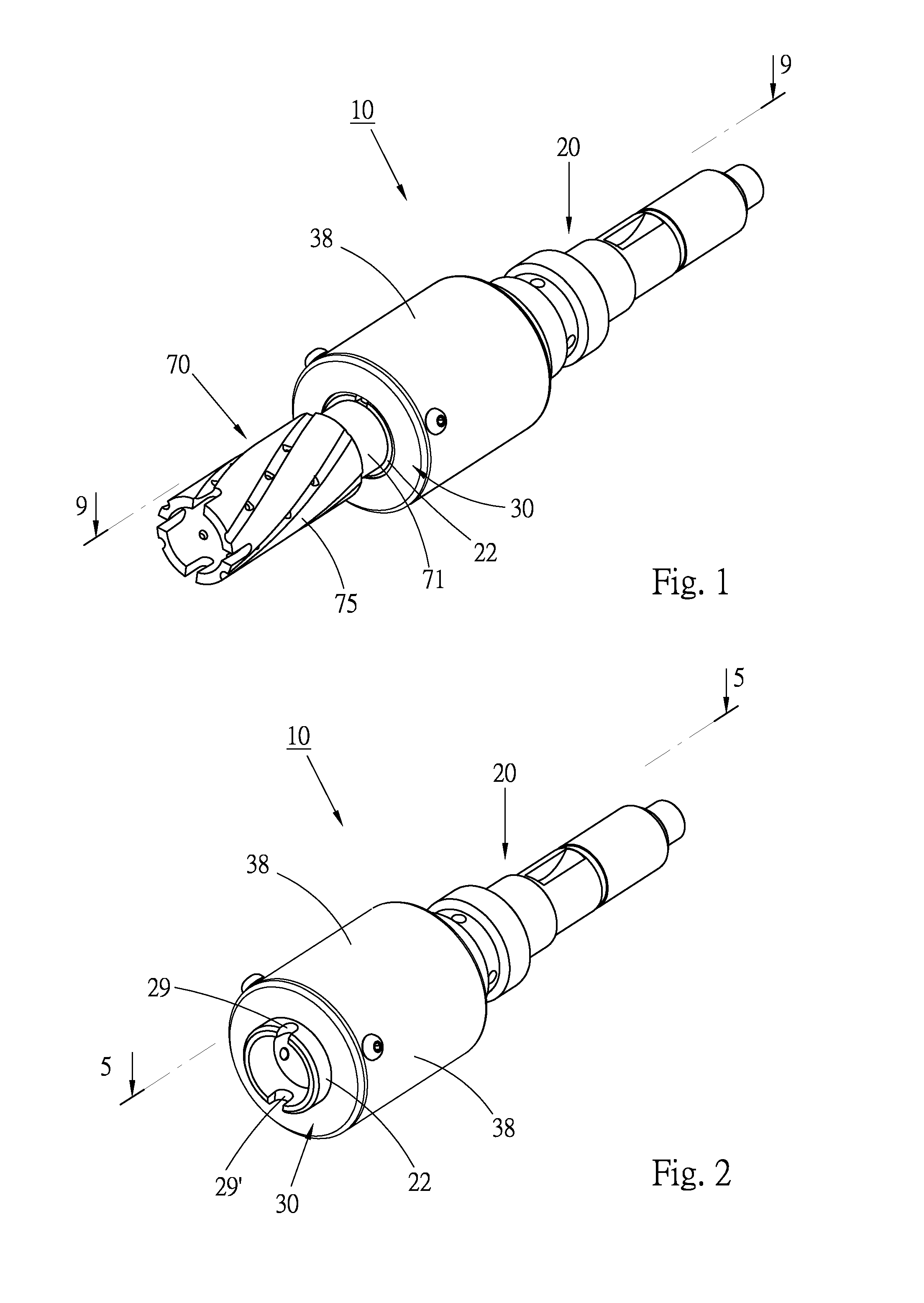
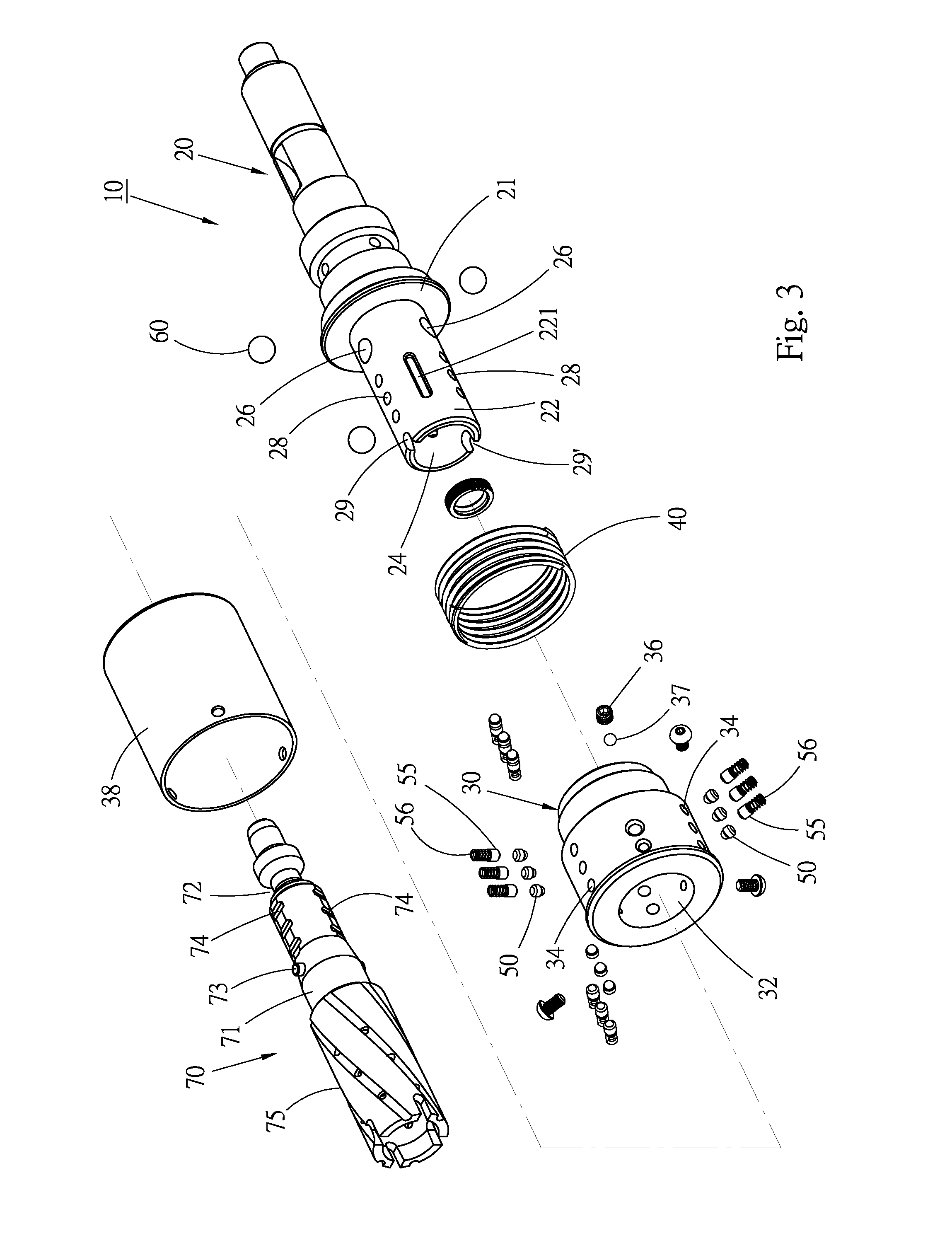
[0033]Please refer to FIGS. 1 to 4. According to a first embodiment, the cutting tool assembly of the present invention includes a mandrel member 10 and a cutting tool 70. The cutting tool assembly is installed on a rotary shaft of a tool machine with cutting or grinding function and rotatable with the rotary shaft for cutting or grinding a work piece. The mandrel member 10 is installed on the rotary shaft of the tool machine or is a part of the rotary shaft. The cutting tool 70 is, but not limited to, a tool with cutting or grinding function. In the description, claims and drawings, the cutting tool assembly is horizontally positioned for illustration purposes. With respect to a machine with a vertical rotary shaft, the present invention is installed on the rotary shaft in a vertical state.

[0034]The mandrel member 10 has a shaft rod 20 and a slide sleeve 30 mounted on the shaft rod 20.

[0035]Please refer to FIGS. 1 to 5. The shaft rod 20 has a front end, which is a sleeve section 22...


PUM

PropertyMeasurementUnit
inner circumferenceaaaaaaaaaa
outer circumferenceaaaaaaaaaa
elastic forceaaaaaaaaaa

Abstract

A cutting tool assembly includes a mandrel member and a cutting tool. The mandrel member has a shaft rod and a slide sleeve fitted around the shaft rod. At least one alignment pin is mounted in the shaft rod and at least one engagement pin is disposed in the slide sleeve. At least one locking member is disposed between the shaft rod and the slide sleeve. The cutting tool has a shank body and a tool bit. At least one alignment sink is disposed on the shank body. When assembled, the shank body is plugged into the shaft rod to align the alignment pin with the alignment sink so as to release the slide sleeve from the engagement of the engagement pin, permitting the slide sleeve to move to a locking position where the locking member is latched with the cutting tool.

Description

BACKGROUND OF THE INVENTION[0001]1. Field of the Invention[0002]The present invention relates generally to a cutting tool of a mechanical apparatus, and more particularly to a fast knockdown cutting tool assembly.[0003]2. Description of the Related Art[0004]A conventional tool machine with cutting or grinding function has a rotary shaft and a cutting tool installed on the rotary shaft. A power source of the tool machine serves to drive the rotary shaft to rotate, whereby the cutting tool can cut or grind a work piece.[0005]A free end of the rotary shaft is provided with a holding device for holding the cutting tool. The cutting tool can be taken off from the holding device and replaced with another cutting tool.[0006]In the conventional structure, it is often necessary to repeatedly align the cutting tool with the holding device for the holding device to truly hold the cutting tool. Therefore, it is time-consuming and inconvenient to install or uninstall the cutting tool.[0007]Moreo...

Claims


Application Information

Patent Timeline
Patent Type & Authority Patents(United States)
IPC IPC(8): B23B31/107B23C5/26B23B31/00B23B51/04B24D5/06B23B31/22
CPCB23C5/26B23B31/005B23B31/1071B23B51/0473B24D5/06Y10T408/907Y10T408/95B23B31/107B23B31/22Y10T279/17752Y10T279/17743Y10T408/953Y10T279/17811B23B2231/0268B23B2231/028Y10T409/30952
Inventor LI, KUANG-TAI
Owner GISON MASCH CO LTD
Why Eureka
Try Eureka