Apparatus for unloading a cargo space

a cargo space and apparatus technology, applied in the direction of conveyors, special-purpose vessels, waterborne vessels, etc., can solve the problems of labor-intensive, unloading stackable cargo units from a cargo space, and many distribution centers, however, are not large enough to install such an expensive system, so as to save (heavy) work and time, and increase the flexibility of the apparatus. , the effect of reducing physical stress

Inactive Publication Date: 2009-03-12
COPAL HLDG
View PDF13 Cites 12 Cited by
  • Summary
  • Abstract
  • Description
  • Claims
  • Application Information

AI Technical Summary

Benefits of technology

[0013]By using an array of suction cups that more small stackable cargo units can be picked up at a time, whereas large stackable cargo units—which often will be heavier—can still be picked up in a reliable way since they are held by more suction cups than small stackable cargo units. In the present application, a suction cup is meant to be a suction cup that is provided with underpressure during operation, also designated as vacuum. The underpressure can be achieved by enlarging the lumen of the suction cup that seals against a stackable cargo unit or, preferably, by removing air from the lumen of the suction cup. In this way, an apparatus is provided which makes it possible to take out stackable cargo units in a very limited space in such a way that the personnel who operate it experience little physical stress. This is how it works: using the arm, the stackable cargo units are placed near the distal end of the conveyor track onto the conveyor track of the apparatus according to the invention and are transported from the distal end in the direction of the proximal end (i.e. in the first transport direction), where the distal end of the conveyor track is brought into the cargo space during unloading. It is conceivable that the apparatus is a stationary apparatus, and that the cargo space is moved relative to the apparatus. However, the apparatus is preferably mobile so that it can be used at more locations such as more docks or transfer stations. As the cargo space is unloaded further, the distal end of the conveyor track is brought deeper into in...

Problems solved by technology

Unloading stackable cargo units from a cargo space, such as a cargo space of a truck or a maritime container, i...

Method used


Image

  • Apparatus for unloading a cargo space
  • Apparatus for unloading a cargo space
  • Apparatus for unloading a cargo space

Examples


Embodiment Construction

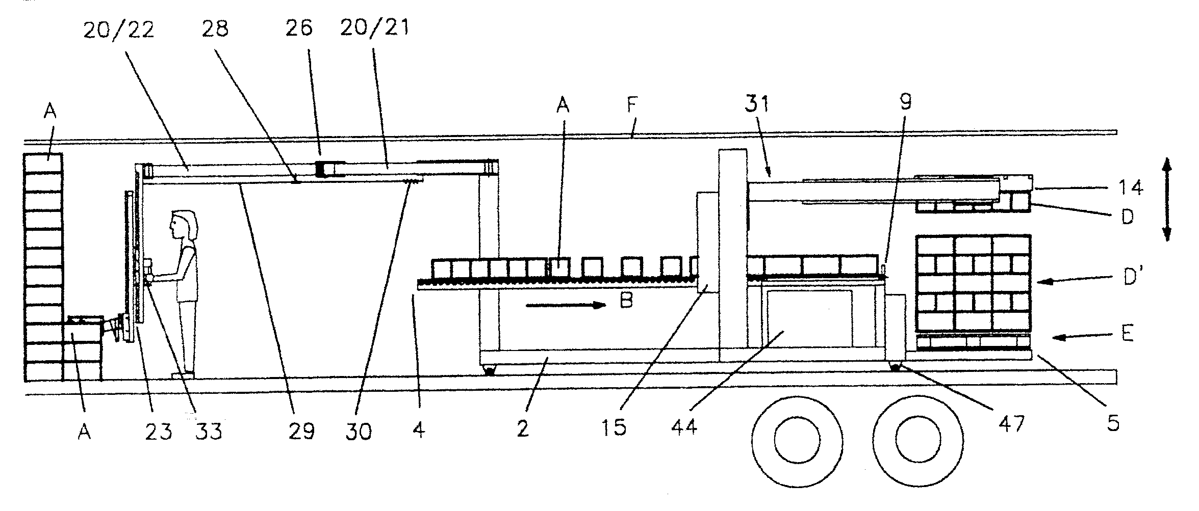
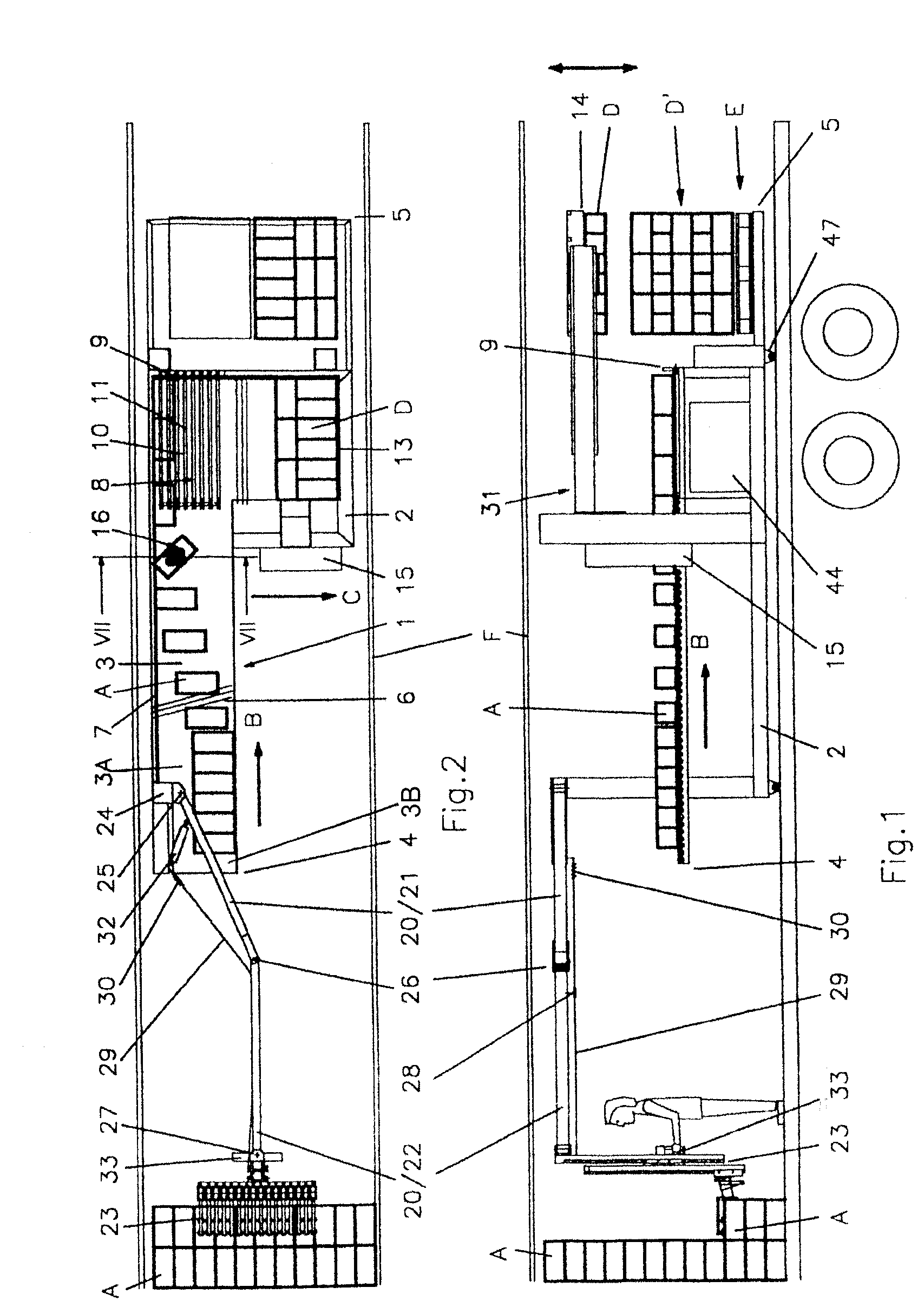
[0014]A preferred embodiment is characterized in that the frame is provided with a first vertical axis, the arm is a hinging arm which comprises a first arm member and a second arm member wherein a first arm member is connected to the frame such that it can rotate around the first vertical axis, a second vertical axis connects the first arm member and the second arm member, and the head is connected to the second arm member via a third vertical axis.

[0015]Such a hinging arm is strong and efficient. A hinging arm can bridge a large distance. In the framework of the present invention the term “vertical” is understood to mean substantially at a right angle to the bottom of the cargo space, since deviations from the normal are permissible as long as these deviations do not hinder the work in the limited space of the cargo space such as a maritime container.

[0016]In order to further facilitate the personnel's work, the apparatus is preferably designed such that the second arm member is p...


PUM


Abstract

An apparatus for unloading a cargo space, such as a maritime container, which contains stackable cargo units. The apparatus comprises a frame which is provided with an active conveyor track having a distal end and a proximal end, wherein the dimensions of at least a part of the frame with the conveyor track are such that it can be brought into the cargo space, the frame near the distal end is provided with a movable arm, wherein the movable arm is provided with a head for picking up at least one stackable cargo unit. According to the invention the head comprises an array with vertically directed suction cups, which array can be moved in the vertical direction for picking up at least one stackable cargo unit at its upper side.

Description

CROSS-REFERENCE TO RELATED APPLICATIONS[0001]This application is a continuation-in-part application of International Patent Cooperation Treaty Application Serial No. PCT / NL2006 / 000242, entitled “Apparatus for Unloading a Cargo Space”, to Jozef G. H. M. Schenning, filed on May 8, 2006, and the specification and claims thereof are incorporated herein by reference.[0002]This application claims priority to and the benefit of the filing of Netherlands Patent Application Serial No. NL 1028990, entitled “Apparatus for Unloading a Cargo Space”, filed on May 9, 2005, and the specification and claims thereof are incorporated herein by reference.STATEMENT REGARDING FEDERALLY SPONSORED RESEARCH OR DEVELOPMENT[0003]Not Applicable.INCORPORATION BY REFERENCE OF MATERIAL SUBMITTED ON A COMPACT DISC[0004]Not Applicable.COPYRIGHTED MATERIAL[0005]Not Applicable.BACKGROUND OF THE INVENTION[0006]1. Field of the Invention (Technical Field)[0007]The present invention relates to an apparatus for unloading ...

Claims


Application Information

Patent Timeline
IPC IPC(8): B65G67/60B65G69/00
CPCB65G47/914B65G47/918B65G67/20B65G2201/025B65G57/24
Inventor SCHENNING, JOZEF G.H.M.
Owner COPAL HLDG
Why Eureka
Try Eureka