
Method of manufacturing and structure of prestressed composite reinforcements

a composite reinforcement and prestressed technology, applied in the field of composite reinforcement bandages, can solve the problems of reducing the precompression of the ceramic liner at elevated temperatures, imposing tight restrictions on the accuracy of both the sleeve and the liner, and not achieving the specified combination of the goals of alternative reinforcement approaches presented in literature and other inventions, and achieves a wide range of deformation.

Active Publication Date: 2015-08-18
PULNIKOV ANDREY
View PDF1 Cites 5 Cited by
  • Summary
  • Abstract
  • Description
  • Claims
  • Application Information

AI Technical Summary

Benefits of technology

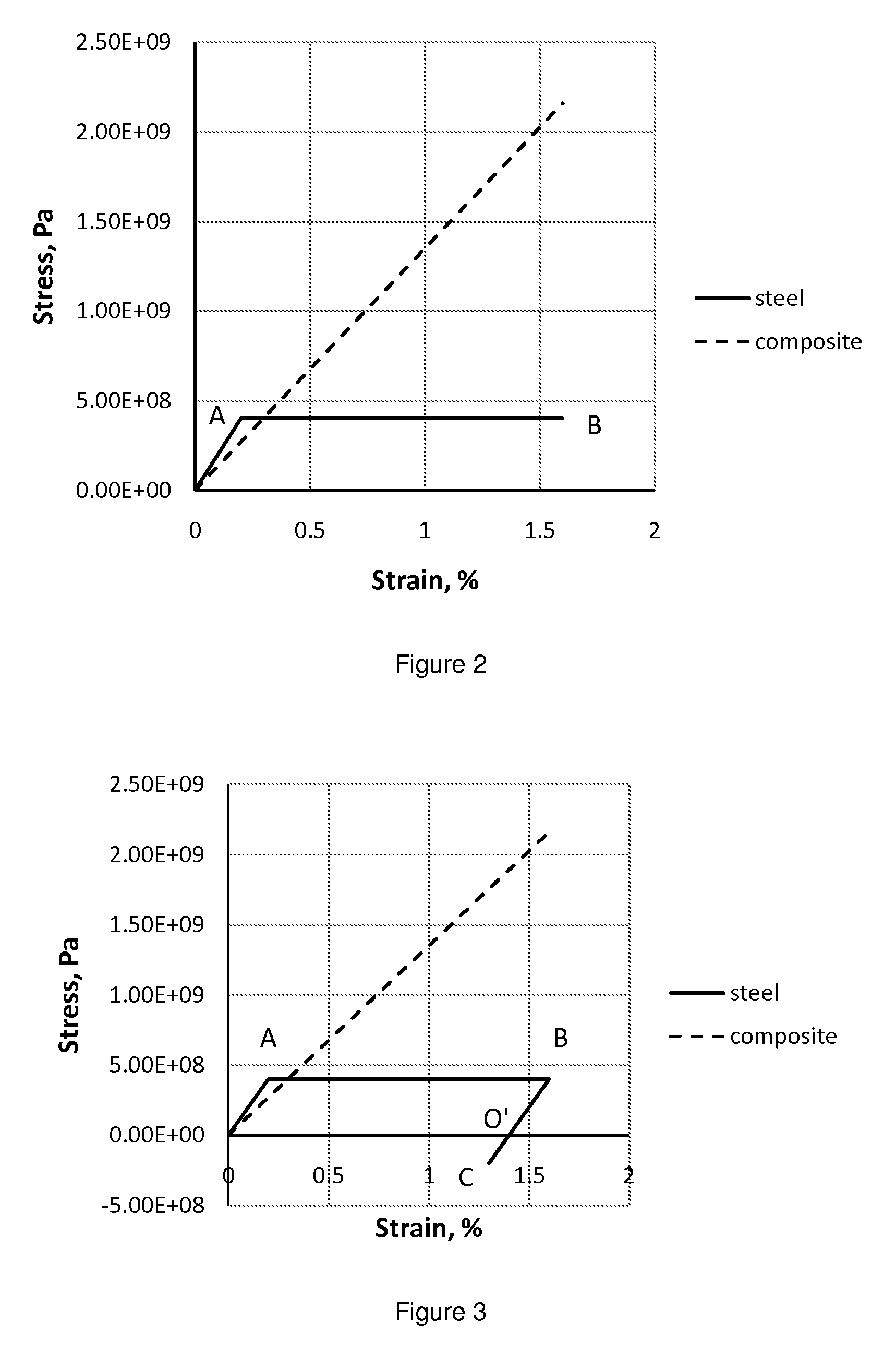
[0011]Modern high-strength materials, such as fiber reinforced composites and metal wires, typically have a much larger deformation range compared to the deformation range of the liner. Introduction of pretension into the reinforcement and according precompression of the liner can help balance deformation ranges of two materials. Thereby a complete use of mechanical properties of both the liner and reinforcement could be reached, which would enable substantial mass reduction.
[0012]The maximum weight reduction could be achieved if fiber-reinforced composites are used, because these materials generally have superior strength and low density. However it is important to apply pretension when the composite has achieved its full strength. In case of a polymer matrix, this situation is reached when the polymer is fully cured. The composite tow should have sufficient number of fibers in order to reduce effect of defects spread along the length of fibers. When the composite has its full strength, winding under pretension could be implemented.

Problems solved by technology

Alternative reinforcement approaches presented in literature and other inventions do not allow achieving the specified combination of these goals.
This approach has a number of disadvantages, such as inconsistency of thermomechanical properties of the sleeve and the base tube, leading to reduction of precompression of the ceramic liner at elevated temperatures.
This approach imposes very tight restrictions on the accuracy of both the sleeve and the liner.
Tension in the steel sleeve is non-uniform, which means that the sleeve material is not used fully.
The braided structure would not permit high levels of precompression in the liner due to considerable deflection of fibers from the hoop direction.
Besides, loading fibers before the polymer is cured would not allow achieving substantial levels of pretension.
Fibers contain various defects along their length and these defects generally determine the strength of fibers and eventually of the whole bundle.
This leads to low pretension and inefficient use of the reinforcement as well as incomplete use of the properties of the ceramic liner.
This approach is also fairly inefficient at least in providing radial reinforcement, because metal and composite have different elastic limits.
This would increase the cost, impede cooling of the liner during firing and increase the total weight of the component.
The overall mass reduction in this case is unsubstantial.
Since pretension is applied at an inappropriate moment, when the strength of the composite is fairly low, the applied pretension is also low and the use of the material of reinforcement is inefficient.
However since the matrix was melt, the pretension applied to the tow was low compared to the tension that could be applied to the dry tow.
This happens because the fibers get some freedom when matrix is melt leading to increased effect of fiber defects and overall reduction of the strength of the tow.
Thus the most common mistake made in alternative approaches is that the properties of the composite reinforcement and the liner are not used fully.

Method used


Image

  • Method of manufacturing and structure of prestressed composite reinforcements
  • Method of manufacturing and structure of prestressed composite reinforcements
  • Method of manufacturing and structure of prestressed composite reinforcements

Examples


Embodiment Construction

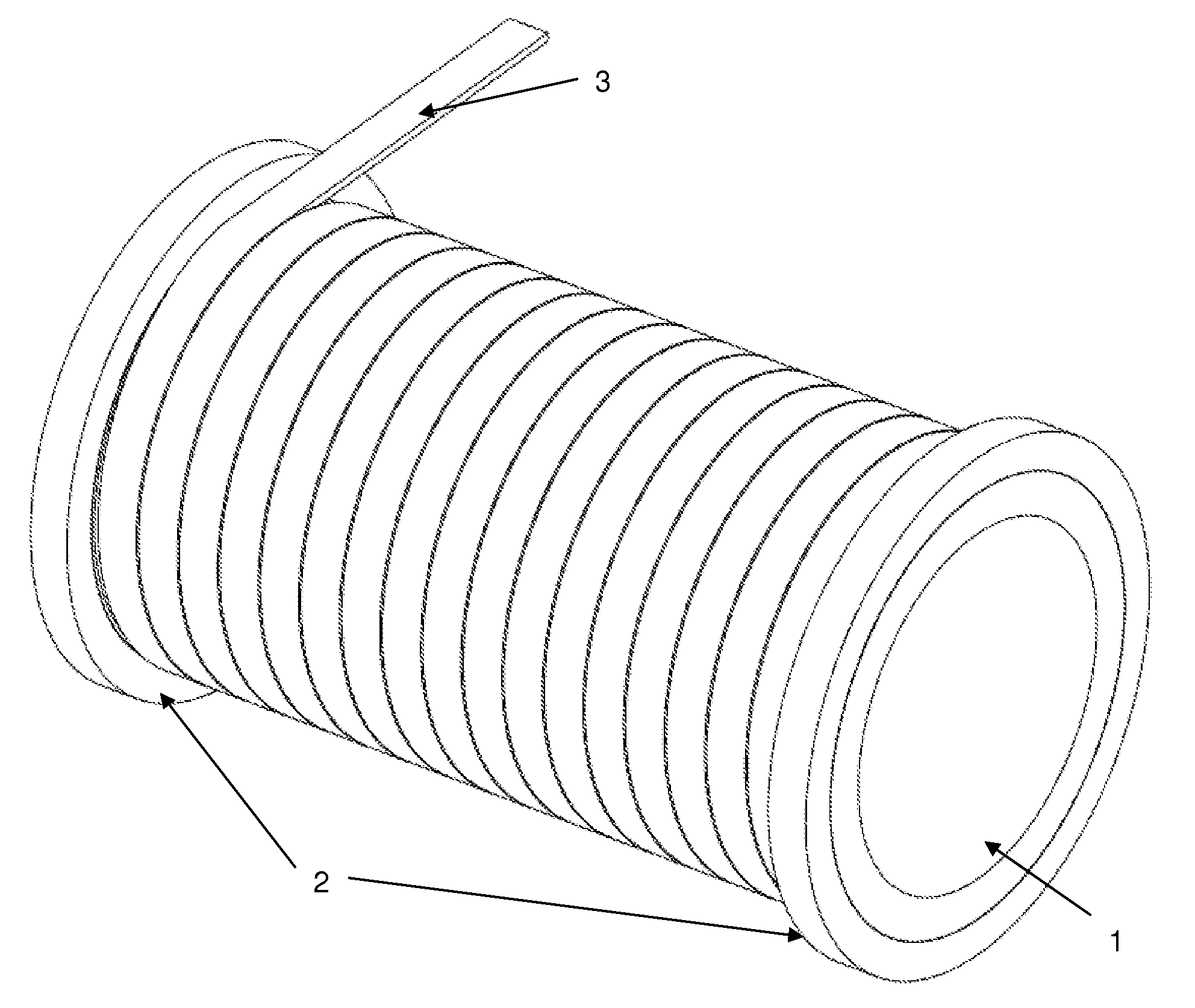
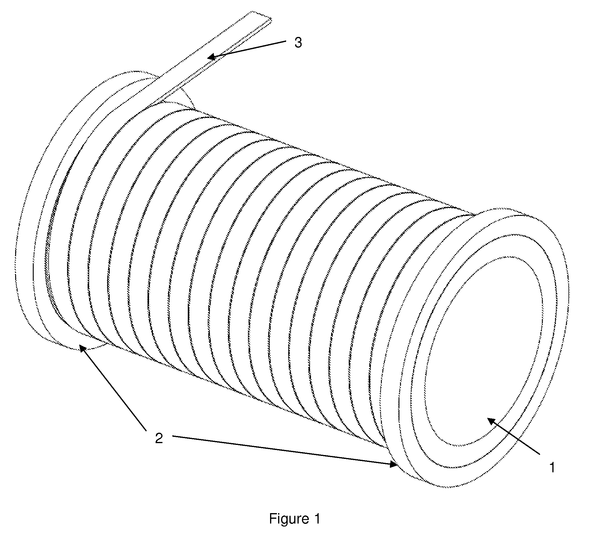
[0030]If a cylindrical part is subjected to internal pressure or centrifugal loads, it is in most cases sufficient to provide radial reinforcement. This reinforcement could be implemented by direct winding under pretension using fiber reinforced tape. The type of the matrix is irrelevant as long as it satisfies the requirement of distributing the load among the fibers. All available matrix materials would generally be usable with a preference to thermoset, thermoplast polymer matrices and metal matrices. So either a fully cured thermoset fiber reinforced tape or tow, or a fiber reinforced thermoplast matrix tape or tow, or a fiber reinforced metal matrix tape or tow or any combination of such tapes or tows would be usable. As mentioned above, drawn steel wires or generally metal wires could also be suitable candidates for the reinforcement, if, for instance, application requires minimization of costs rather than minimization of weight, because steel wires are cheaper compared to pul...


PUM

PropertyMeasurementUnit
tensile strengthaaaaaaaaaa
tensile strainaaaaaaaaaa

Abstract

In this invention a method of manufacturing and structure of prestressed composite reinforcements for cylindrical liners is presented. The method relies on creating deep precompression in the liner compensated by according pretension in the reinforcement. This method allows efficient use of mechanical properties of material of the liner and reinforcement and can provide a substantial mass reduction of the overall component.

Description

TECHNICAL FIELD[0001]This invention is related to composite reinforcement bandages. The technique proposed in this invention could be useful for components subjected to internal pressure or high centrifugal loads.BACKGROUND INFORMATION[0002]This invention is related to fiber reinforced bandages and containment solutions for high-speed applications as well as for devices and components operating at high internal pressure. This invention is particularly useful when a light weight solution is necessary.[0003]The purpose of this invention is to provide reinforcement of cylindrically shaped components with the goal of substantial mass reduction, reliable operation under load and in the whole operational temperature range. Another purpose of this invention is to facilitate manufacturing of such a reinforcement.[0004]Alternative reinforcement approaches presented in literature and other inventions do not allow achieving the specified combination of these goals.[0005]In U.S. Pat. No. 4,401,...

Claims


Application Information

Patent Timeline
Patent Type & Authority Patents(United States)
IPC IPC(8): B29C70/56
CPCB29C70/56
Inventor PULNIKOV, ANDREY
Owner PULNIKOV ANDREY
Learn More