
Optical diffusing film and a liquid crystal display backlight using the same

a liquid crystal display and optical diffusing film technology, applied in the field of display technology, can solve the problems of limited shielding ability and light-converging ability, and achieve the effects of less assembled elements, higher haze and luminance, and less assembled elements

Active Publication Date: 2015-08-18
CHINA LUCKY FILM CORP +2
View PDF12 Cites 0 Cited by
  • Summary
  • Abstract
  • Description
  • Claims
  • Application Information

AI Technical Summary

Benefits of technology

[0005]The present invention is carried out in view of the above-mentioned defects in the art, and the objects thereof are to provide an optical diffusing film with stronger light-converging ability, enhanced haze and luminance, and to provide a LCD backlight using the same.
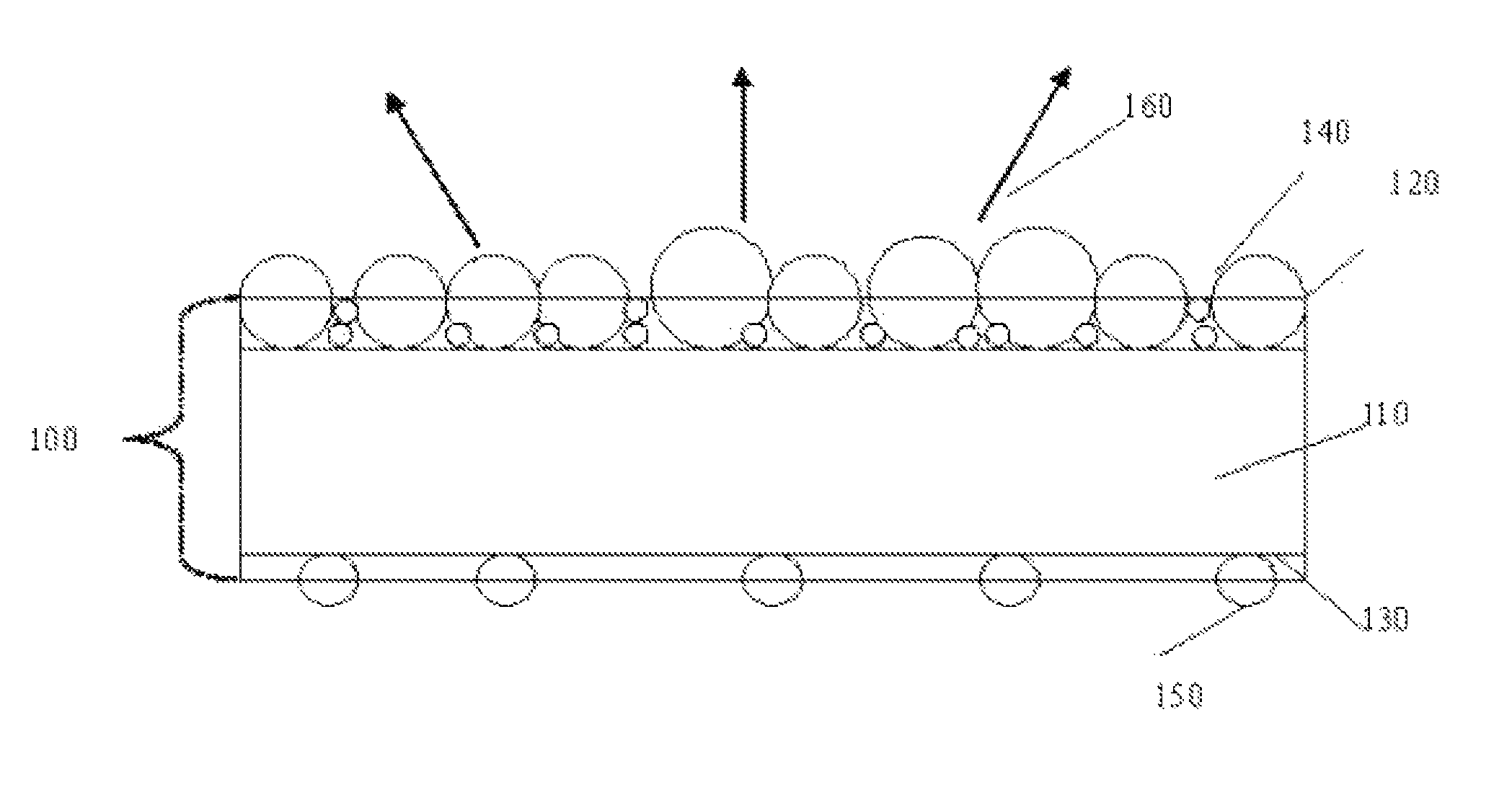
[0013]Compared with the optical diffusing film in the prior art, the optical diffusing film according to the present invention has advantages of having higher haze and light-converging ability, by controlling the particle size, arrangement, and amount per unit area of the spherical diffusing particles in the diffusing coating thereof and thickness of the diffusing coating.
[0014]An optical diffusing film in a specific embodiment according to the present invention further comprises an antiblocking coating with antiblocking particles, so that when the optical diffusing film is used in a backlight module for a display, a thin air layer can be formed between the optical diffusing film and other elements in the module, thereby preventing the optical diffusing film from adhering with other elements.
[0015]Similarly, the liquid crystal display backlight obtained by using the above-mentioned optical diffusing film according to the present invention has advantages of having less assembled elements, and higher haze and luminance.

Problems solved by technology

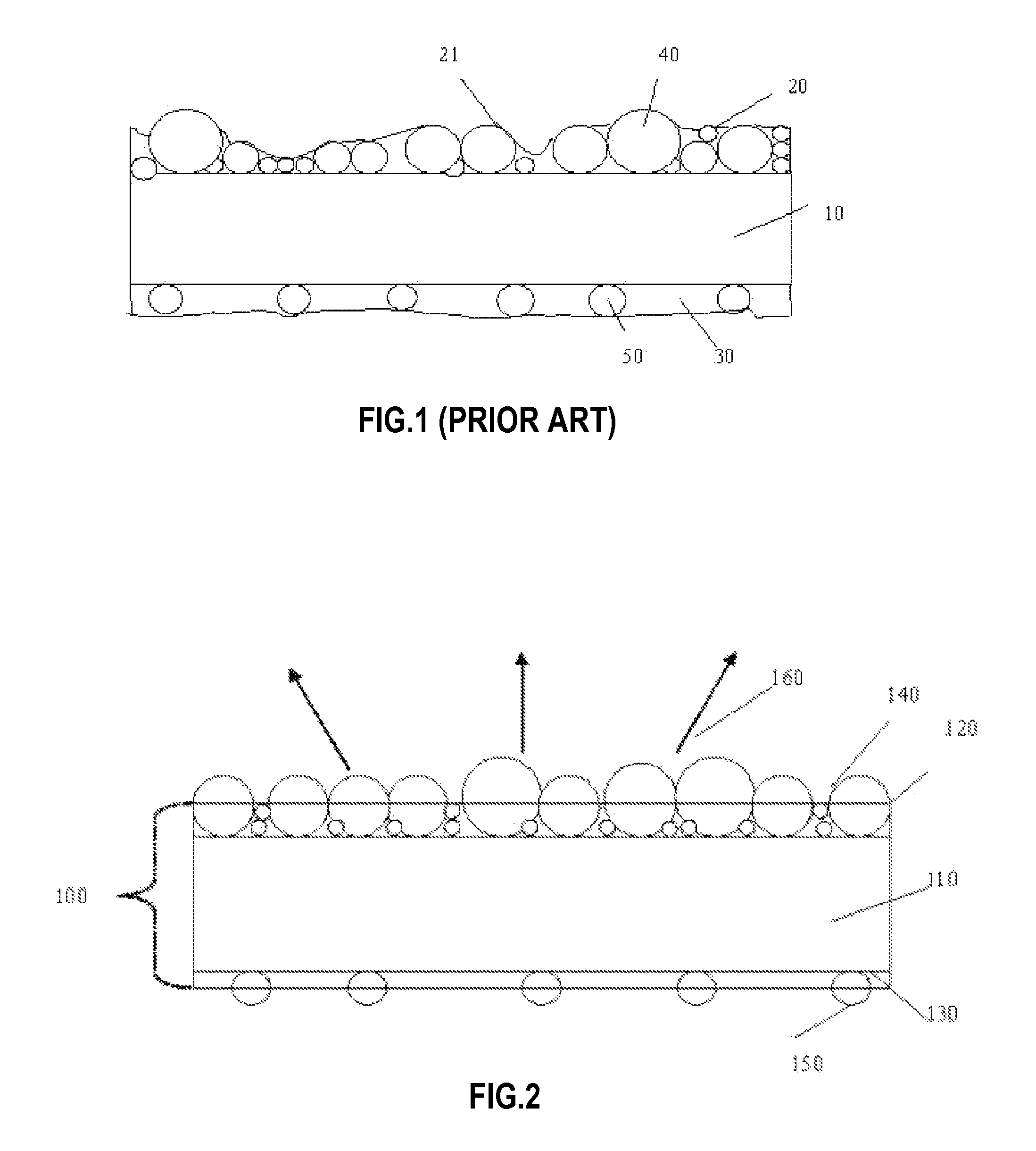
Thus, there is a problem in the afore-said film that, the light-converging ability and the shielding ability is limited.

Method used


Image

  • Optical diffusing film and a liquid crystal display backlight using the same
  • Optical diffusing film and a liquid crystal display backlight using the same
  • Optical diffusing film and a liquid crystal display backlight using the same

Examples


example 1

[0052]As shown in FIG. 2, an optical diffusing film 100 comprises a transparent PET substrate 110, a diffusing coating 120 containing spherical PMMA diffusing particles 140, and an antiblocking coating 130 containing spherical PMMA antiblocking particles 150. The diffusing particles in different particle sizes in the diffusing coating 120 are being combined in the ratio as shown in Table 1, in which those large diffusing particles 140 are arranged firmly together in the diffusing coating 120, and those small diffusing particles 140 are dispersed and filled within the diffusing coating 120, and light can be diffused due to the differences of refractive indexes among the small diffusing particles 140, substrate 110 and diffusing coating. The thickness of the diffusing coating 120 is strictly controlled to half of the particle size of those large diffusing particles 140, that is, half part of those large diffusing particles 140 are embedded in the diffusing coating 120, and the other h...

example 2

[0054]As shown in FIG. 2, an optical diffusing film 100 comprises a transparent PET substrate 110, a diffusing coating 120 containing spherical PS diffusing particles 140, and an antiblocking coating 130 containing spherical PMMA antiblocking particles 150. The diffusing particles in different particle sizes in the diffusing coating 120 are being combined in the ratio as shown in Table 2, in which those large diffusing particles 140 are arranged firmly together in diffusing coating 120, and those small diffusing particles 140 are dispersed and filled within the diffusing coating 120, and light can be diffused due to the differences of refractive indexes among the small diffusing particles, substrate 110 and resin coating. The thickness of the diffusing coating 120 is strictly controlled to ⅗ of the particle size of those largest diffusing particles 140, that is, along the thickness direction, the embedded portion of those largest diffusing particles 140 in the diffusing coating 120 ...

example 3

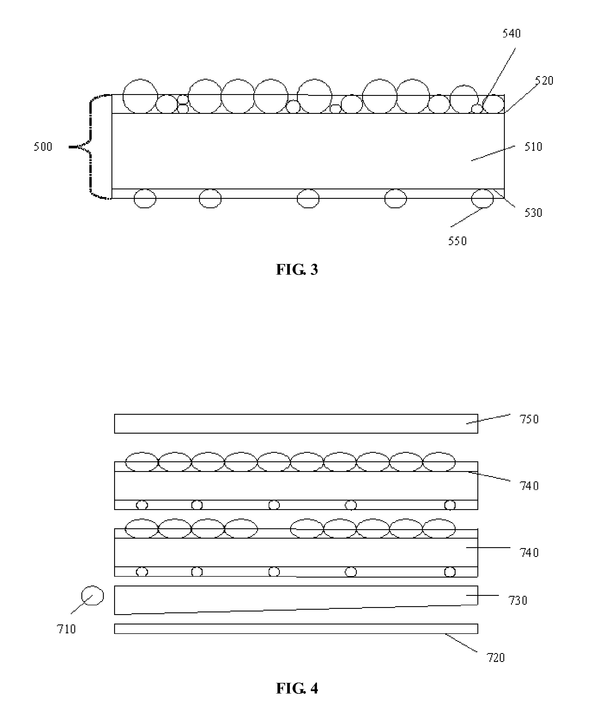
[0056]An optical diffusing film comprises a transparent PET substrate, a diffusing coating containing spherical PMMA diffusing particles, and an antiblocking coating containing spherical PMMA antiblocking particles. The diffusing particles in different particle sizes in the diffusing coating are being combined in the ratio as shown in Table 3, and they are arranged firmly together in the diffusing coating. The thickness of the diffusing coating is strictly controlled to ⅔ of the particle size of the largest diffusing particles. The antiblocking coating comprises antiblocking particles with a particle size of 2 μm, and the antiblocking particles are arranged sparsely and randomly in the antiblocking coating, and the coating density thereof is 500 particles per square millimeter. The thickness of the antiblocking coating is ⅗ of the particle size of antiblocking particles, and a thin air layer can be formed between the antiblocking coating and other members of module because of the pa...


PUM

PropertyMeasurementUnit
refractive indexaaaaaaaaaa
diameteraaaaaaaaaa

Abstract

An optical diffusing film and a LCD backlight using the same are provided. The optical diffusing film comprises a transparent substrate made of an optically transparent material with a refractive index of 1.4 to 1.8, and a diffusing coating with a refractive index of 1.4 to 1.7 disposed on an upper surface of the transparent substrate, wherein diffusing particles with a refractive index of 1.4 to 1.7 are distributed in the diffusing coating, and the diffusing particles are in close contact with each other, the diffusing coating has a thickness of ½ to ⅔ of the largest particle size of the diffusing particles, and the coating density of the diffusing particles is 103 to 106 particles per square millimeter.

Description

CROSS-REFERENCE TO RELATED APPLICATIONS[0001]The present application claims priority under 35 U.S.C. §365(a) to PCT International Application No. PCT / CN2011 / 082025 to the inventors, filed Nov. 10, 2011, which in turn claims priority under 35 U.S.C. §119(a) to Chinese Patent Application No. 201010572701.4 to the inventors, filed Dec. 3, 2010. The entire contents of each of these applications are hereby incorporated by reference herein.TECHNICAL FIELD[0002]The present invention relates to the field of display technology, and more particularly, to an optical diffusing film and a liquid crystal display (LCD) backlight using the same.BACKGROUND ART[0003]The existing optical diffusing film is widely used in an apparatus requiring light source, such as a LCD backlight, an advertising lightbox, a lighting lamp, keys of mobile communication devices, etc., to provide uniform illumination. In recent years, there has been a strong demand for higher performance of the optical diffusing film used...

Claims


Application Information

Patent Timeline
Patent Type & Authority Patents(United States)
IPC IPC(8): F21V8/00G02B5/02G02F1/1335
CPCG02B6/0043G02B5/0226G02B5/0294G02F1/133606
Inventor ZHAO, BAOLIANGLI, YUHANGWANG, XULIANGHUO, XINLI
Owner CHINA LUCKY FILM CORP
Learn More