Infrared imaging optical system

An optical system and infrared imaging technology, applied in the field of optics, can solve the problems of low light-gathering ability, low precision, difficulty in obtaining high-definition, high-resolution images, etc., and achieve the effect of excellent imaging quality and strong light-gathering ability

Active Publication Date: 2022-02-01
JIHUA LAB
View PDF9 Cites 0 Cited by
  • Summary
  • Abstract
  • Description
  • Claims
  • Application Information

AI Technical Summary

Problems solved by technology

Although patent CN109407273 A realizes the common-aperture design of visible light, mid-wave and long-wave infrared, the relative aperture of the optical system is only F / 4, and the light-gathering ability is low, making it difficult to obtain high-definition and high-resolution images
Fu Qiang et al. studied the design elements of the co-aperture infrared dual-band optical system in the 2015 Journal of Optics "Material Selection for Medium-Wave / Long-Wave Dual-color Infrared Optical System", but the obtained design result is still a small relative aperture optical system, which is difficult to meet the infrared The imaging system pursues the needs of high light-gathering ability and high sensitivity
[0004] The common-aperture mid- and long-wave infrared imaging optical system is a key way to solve the problem of large volume and low precision of discrete infrared optical systems
In specific applications, the design of the common-aperture imaging optical path faces the problem of ultra-wide spectrum chromatic aberration and secondary spectrum correction; due to the limited availability of high-transmittance infrared materials that simultaneously satisfy mid-wave infrared and long-wave infrared, it is more difficult to correct aberrations; further Yes, in order to improve the detection sensitivity of the infrared thermal imaging system and give full play to the performance of the infrared dual-color detector, the optical system needs to achieve a large relative aperture design, which also increases the difficulty of correcting and balancing optical aberrations

Method used


Image

  • Infrared imaging optical system
  • Infrared imaging optical system
  • Infrared imaging optical system

Examples


Embodiment Construction

[0057] The technical solutions in this application will be clearly and completely described below in conjunction with the drawings in this application. Obviously, the described embodiments are only some of the embodiments of this application, not all of them. The components of the application generally described and illustrated in the figures herein may be arranged and designed in a variety of different configurations. Accordingly, the following detailed description of the embodiments of the application provided in the accompanying drawings is not intended to limit the scope of the claimed application, but merely represents selected embodiments of the application. Based on the embodiments of the present application, all other embodiments obtained by those skilled in the art without making creative efforts belong to the scope of protection of the present application.

[0058] It should be noted that like numerals and letters denote similar items in the following figures, theref...


PUM

PropertyMeasurementUnit
pore sizeaaaaaaaaaa
pore sizeaaaaaaaaaa
thicknessaaaaaaaaaa

Abstract

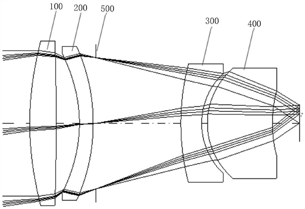
The invention provides an infrared imaging optical system, and relates to the technical field of optics. The system is technically characterized in that the infrared imaging optical system comprises a first lens, a second lens, a third lens and a fourth lens which are sequentially arranged from an object side to an image side along an optical axis; the first lens haspositive focal power; the second lens has negative focal power; the third lens has negative focal power; the fourth lens has positive focal power; the focal power of the first lens is phi 1, the focal power of the whole optical system is phi, and phi 1 / phi is larger than or equal to 0.40 and smaller than or equal to 0.90; the combined focal power of the first lens and the second lens is phi 12, the focal power of the whole optical system is phi, and phi 12 / phi is larger than or equal to 0.35 and smaller than or equal to 0.52; and the combined focal power of the third lens and the fourth lens is phi 34, the focal power of the whole optical system is phi, and phi 34 / phi is larger than or equal to 1.02 and smaller than or equal to 1.42. The infrared imaging optical system provided by the invention has the advantages that the complete common-path design of medium-wave infrared and long-wave infrared is realized, the spatial size of the optical system is reduced, the large-relative-aperture imaging capability is realized, the light gathering capability is high, and the imaging quality is high.

Description

technical field [0001] The present application relates to the field of optical technology, in particular, to an infrared imaging optical system. Background technique [0002] Infrared spectrum has the ability to enhance night vision and detect and identify targets all day, so infrared imaging has a wide range of applications in military and civilian fields. According to the "atmospheric window" in the infrared transmission in the atmosphere, the infrared spectrum can be divided into three categories: short-wave infrared, medium-wave infrared and long-wave infrared. Mid-wave infrared and long-wave infrared imaging detect the thermal radiation of the target itself and realize the imaging of the scene. Both have the ability to penetrate haze, fog and high humidity environments and to image all day long. Mid-wave infrared thermal imaging is suitable for detecting higher-temperature targets, and long-wave infrared is suitable for detecting normal-temperature or low-temperature t...

Claims


Application Information

Patent Timeline
Patent Type & Authority Applications(China)
IPC IPC(8): G02B13/00
CPCG02B13/008G02B13/004Y02P40/57
Inventor 伍雁雄乔健陈太喜
Owner JIHUA LAB
Why Eureka
Try Eureka