Phase synchronization circuit for AC voltage
a phase synchronization and ac voltage technology, applied in the direction of photovoltaic energy generation, pulse automatic control, emergency power supply arrangements, etc., can solve the problems of pid having a shortfall of providing lower results for the cost of providing pid, damage or fire to high-precision equipment and instruments, etc., to reduce the burden on the micro controller unit and reduce the number of computations it needs. , the effect of reducing the complexity of the circui
- Summary
- Abstract
- Description
- Claims
- Application Information
AI Technical Summary
Problems solved by technology
Method used
Image

Examples
third embodiment
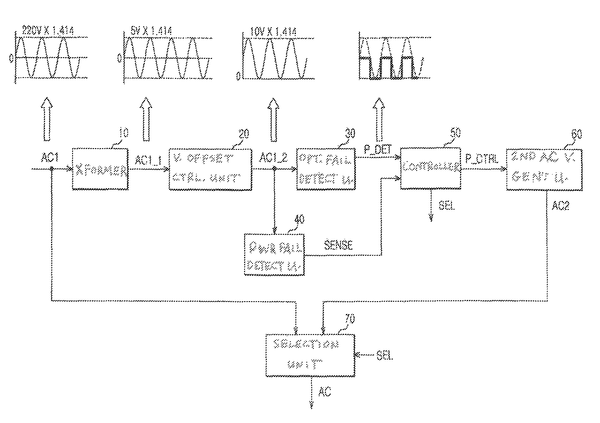
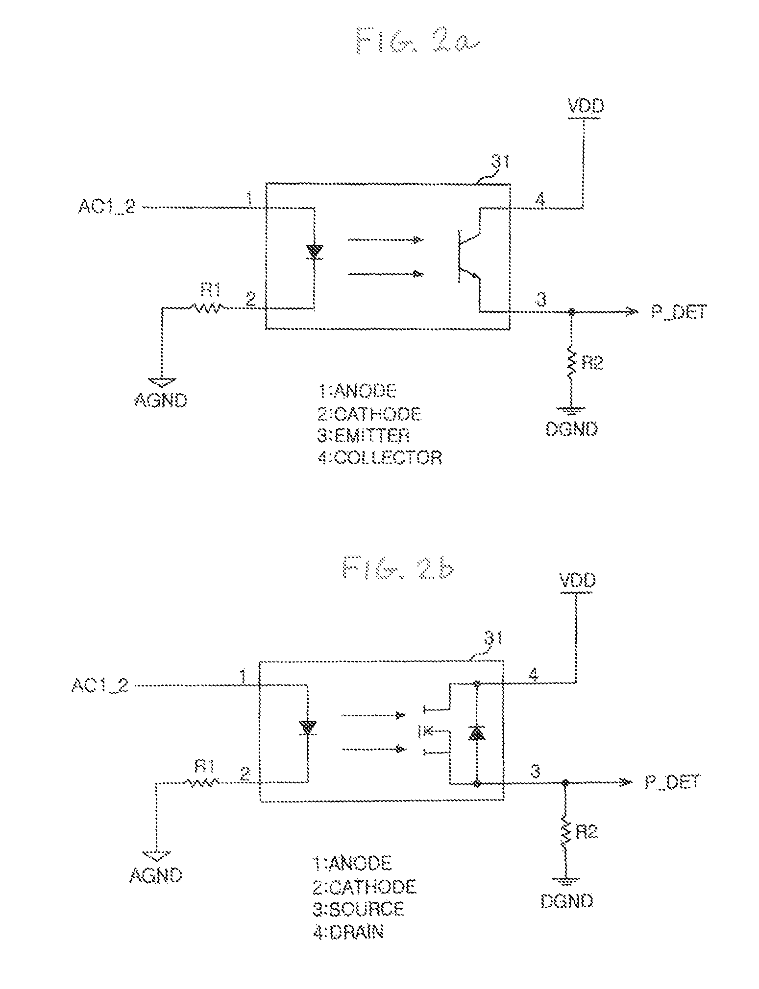
[0032]FIG. 2c shows a optical phase detection unit of FIG. 1 according to the present invention. The optical phase detection unit of FIG. 2c utilizes a plurality of switching elements 31_1, 31_2, 31_3 and the first resistances R1_1, R1_2, R1_3, each of which having different resistance value, and generates a plurality of phase detection signals P_DET_HIGH, P_DET_CENTER, P_DET_LOW. The phase detection unit can detect the different phases of the second internal voltage AC1_2 and output a plurality of phase detection signals P_DET_HIGH, P_DET_CENTER, P_DET _LOW and provide them to the control unit 50.
[0033]This allows the second AC voltage generation unit 60 to have more precise control of synchronizing the second AC voltage AC2 with the phase of the first AC voltage AC1.
first embodiment
[0034]FIG. 3a shows the power failure detection unit according to the present invention, and FIG. 3b shows the power failure detection unit according a second embodiment of the present invention.
[0035]Referring to FIGS. 3a-3b, the power failure detection part 40 comprises a rectifier 41 that receives the second internal voltage AC1_2 and generates an AC voltage and an optical switching element 42 that detects whether the AC voltage is above a predetermined level and outputs a power failure detection signal SENSE.
[0036]According to an embodiment of the present invention, the rectifier 41 comprises a plurality of diodes D1, D2, D3, D4 that form a bridge rectifier circuit and a capacitor C1 that stores the signal outputted from the plurality of diodes D1, D2, D3, D4 and outputs a AC voltage.
[0037]In FIG. 3a, when there is no power failure, voltage level of the power failure detection signal SENSE that is outputted from the output terminal of the optical switching element 42 is a low le...
PUM
 Abstract
Description
Claims
Application Information
 - R&D
- Intellectual Property
- Life Sciences
- Materials
- Tech Scout
- Unparalleled Data Quality
- Higher Quality Content
- 60% Fewer Hallucinations
Browse by: Latest US Patents, China's latest patents, Technical Efficacy Thesaurus, Application Domain, Technology Topic, Popular Technical Reports.
© 2025 PatSnap. All rights reserved.Legal|Privacy policy|Modern Slavery Act Transparency Statement|Sitemap|About US| Contact US: help@patsnap.com