Phase controlled dimming LED driver system and method thereof

a technology of led driver and phase control, applied in the direction of electric variable regulation, process and machine control, instruments, etc., can solve the problem of overcoming several problems

Active Publication Date: 2011-06-23
SAVANT TECH LLC
View PDF35 Cites 80 Cited by
  • Summary
  • Abstract
  • Description
  • Claims
  • Application Information

AI Technical Summary

Benefits of technology

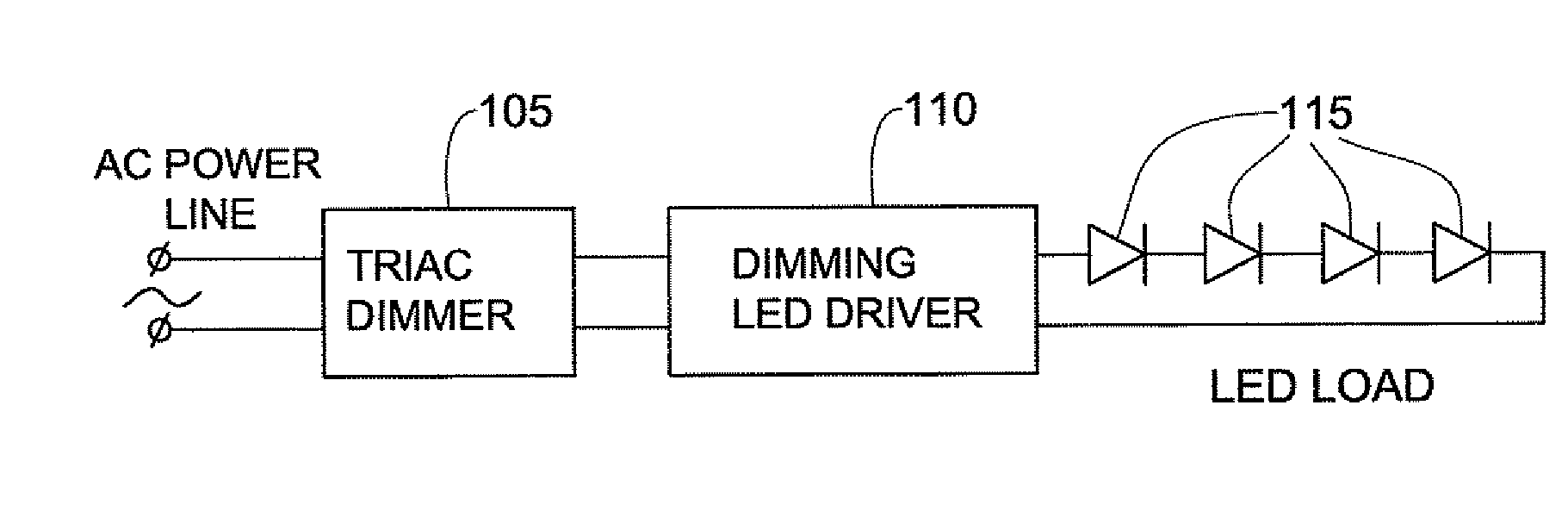
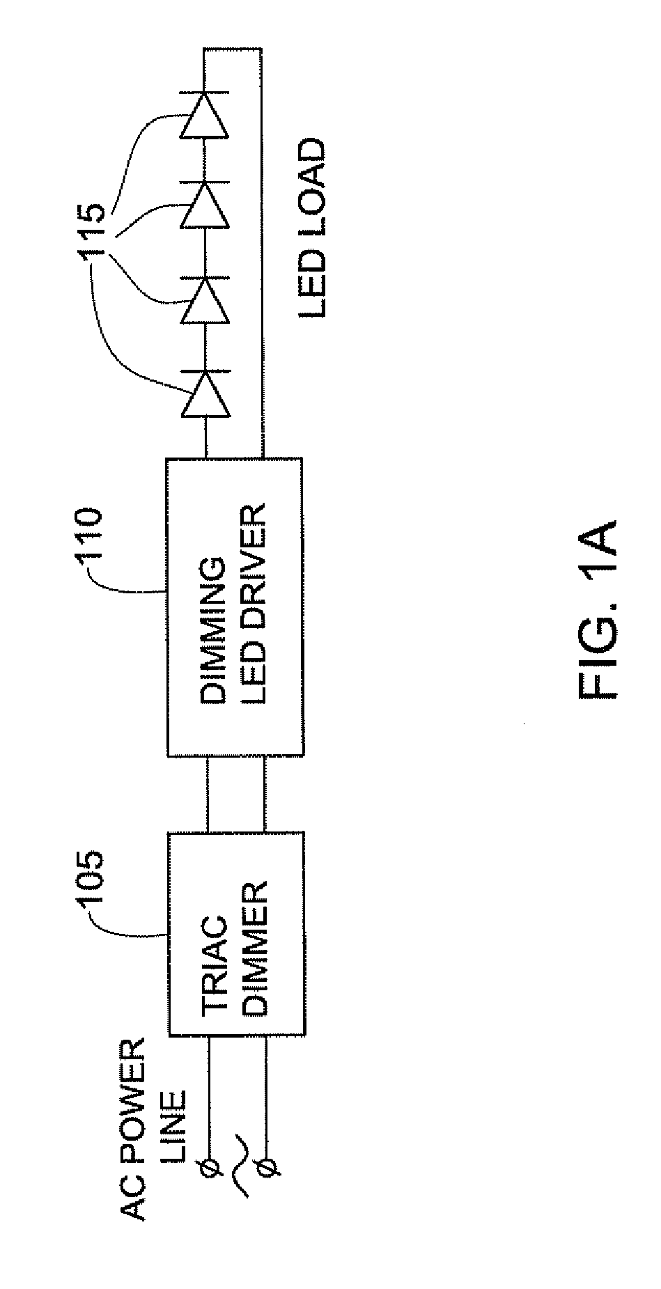
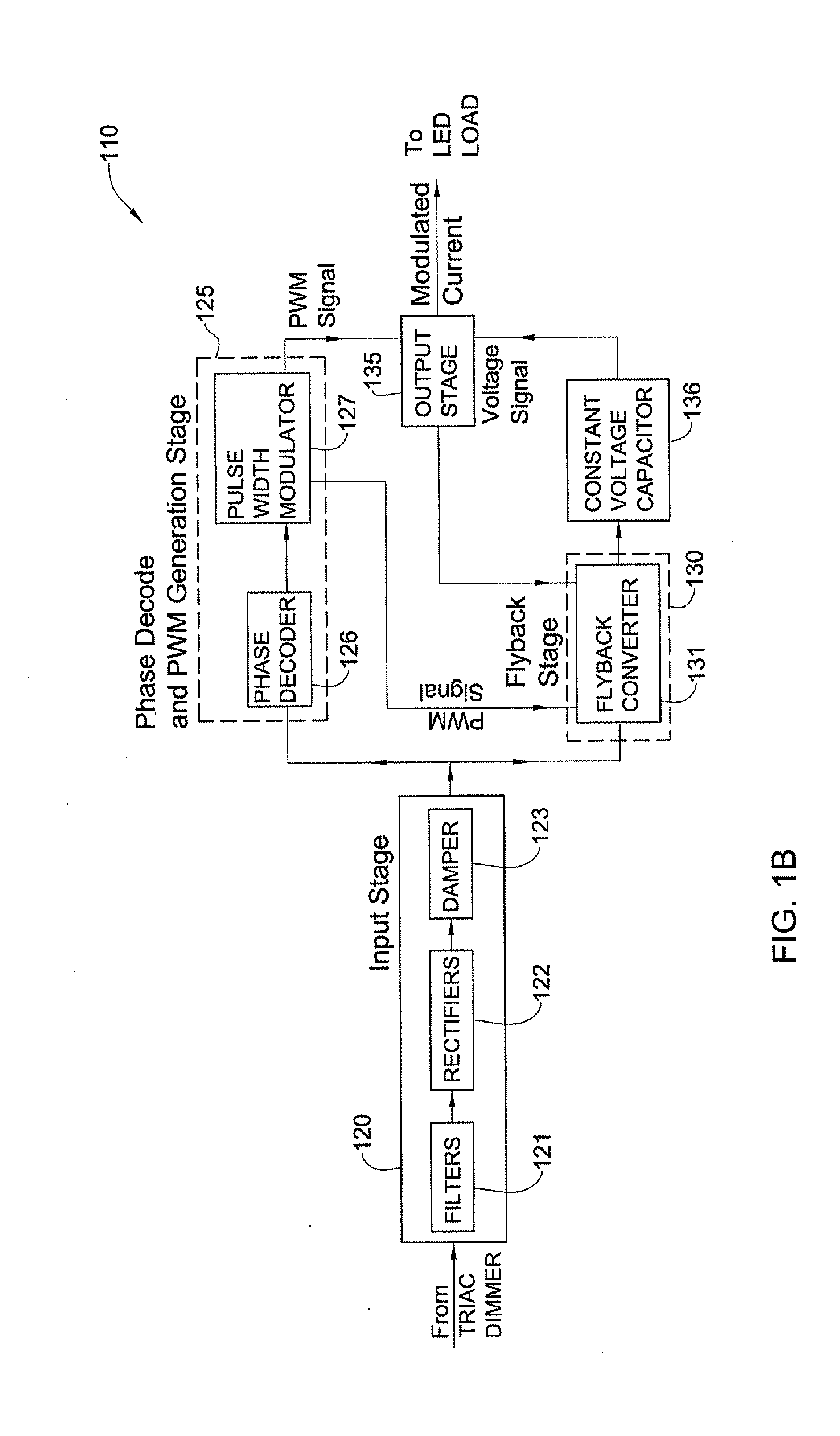
[0040]According to some embodiments of the invention, there is provided a method of enabling dimming the intensity of light generated by at least one light source, comprising: receiving an alternating current (AC) signal from a dimmer; and after receiving the AC signal beginning at substantially the same time to apply amplitude modulation (AM) and pulse width modulation (PWM) to an output current provided to the at least one light source.
[0041]According to some embodiments of the invention, there is provided a method of enabling dimming the intensity of light generated by at least one light source, comprising: receiving an alternating current AC signal from a dimmer; and fine-tuning capacitance and / or resistance using a linear dimming control pin, in order to adjust onset point of dimming of the at least one light source with respect to position of adjusting means of the dimmer.

Problems solved by technology

In recent years, the usage of LED (Light Emitting Diode) illumination instead of other kinds of illumination (such as the fluorescent illumination, incandescent bulb illumination, and the like), has significantly increased due to the increasing luminosity of LED devices and due to their continuously decreasing costs.
However, the use of TRIAC dimmers for other than incandescent lighting requires the overcoming of several problems, such as TRIAC instability.

Method used


Image

  • Phase controlled dimming LED driver system and method thereof
  • Phase controlled dimming LED driver system and method thereof
  • Phase controlled dimming LED driver system and method thereof

Examples


Embodiment Construction

[0058]In the following detailed description, numerous specific details are set forth in order to provide a thorough understanding of the invention. However, it will be understood by those skilled in the art that the present invention may be practiced without these specific details. In other instances, well-known methods, systems, procedures, components, units, circuits and the like have not been described in detail so as not to obscure the present invention.

[0059]Reference in the description to “an embodiment”, “another embodiment”, “a further embodiment”, “this embodiment”, “these embodiments”, “some cases”, “other cases”, “an instance”, “some instances”, “an example”, “some examples” or variants thereof means that a particular feature, structure or characteristic described in connection with the embodiment(s) is included in at least one embodiment of the invention. Thus the appearance of the phrase “an embodiment”, “another embodiment”, “a further embodiment”, “this embodiment”, “...


PUM


Abstract

The present invention relates to providing an improved dimming driver circuitry, system and a method thereof. The dimming driver circuitry is configured to enable dimming intensity of light generated by one or more light sources, the dimming driver circuitry being connected to a dimmer that provides to it an alternating current (AC) signal. The dimming driver circuitry may in some examples not include a processing unit. Additionally or alternatively, the dimming driver circuitry may in some examples apply amplitude modulation to the output current provided to the one or more light sources. In some of these examples, the dimming driver circuitry may begin to apply at substantially the same time pulse width modulation and amplitude modulation to the output current provided to the one or more light sources. Additionally or alternatively, the dimming driver circuitry may in some examples include at least one linear dimming control pin connected to at least one capacitor and/or resistor configured to fine-tune capacitance and/or resistance.

Description

CROSS REFERENCE TO RELATED APPLICATIONS [0001]This application is a continuation in part of U.S. application Ser. No. 12 / 324,948, published on Jun. 3, 2010 as US publication number 2010 / 0134038, which is hereby incorporated by reference herein.FIELD OF THE INVENTION [0002]The present invention relates generally to the field of light dimming control.[0003]Definitions, Acronyms and Abbreviations[0004]Throughout this specification, the following definitions are employed:[0005]AM: is an acronym for Amplitude Modulation, according to which the strength of the signal is varied in relation to the information being transferred.[0006]TRIAC: is an acronym for TRIode for Alternating Current (AC) that is an electronic component / unit approximately equivalent to two silicon-controlled rectifiers joined in inverse parallel (paralleled but with the polarity reversed) and with their gates connected together.[0007]PWM: is an acronym for Pulse Width Modulation of a signal, which involves the modulatio...

Claims


Application Information

Patent Timeline
Patent Type & Authority Applications(United States)
IPC IPC(8): H05B37/02H05B44/00
CPCH05B33/0815H05B33/0851H05B33/0818H05B45/10H05B45/385
Inventor SHACKLE, PETER W.DU, ZHANQI
Owner SAVANT TECH LLC
Why Eureka
Try Eureka