Method and apparatus for load sharing in a multiphase switching power converter

a multi-phase switching and power converter technology, applied in the direction of electric variable regulation, process and machine control, instruments, etc., can solve the problems of reducing the efficiency of input voltage ripple, and reducing the size of input capacitors and output capacitors, so as to reduce cost and power loss, improve reliability, and accurately share current

Inactive Publication Date: 2006-02-28
MICROSEMI CORP ANALOG MIXED SIGNAL GRP LTD
View PDF54 Cites 79 Cited by
  • Summary
  • Abstract
  • Description
  • Claims
  • Application Information

AI Technical Summary

Benefits of technology

[0025]Accurate current sharing ensures that heat and component stresses are evenly distributed in the power conversion circuit, thereby improving reliability. Embodiments in accordance with the present invention achieve accurate current sharing among multiple channels of a switching converter without directly sensing the currents of respective channels, thereby reducing cost and power loss associated with sensing resistors typically used to sense current.

Problems solved by technology

The continuous inductor current rating sets a typical limitation in output current that can be delivered by a single-phase converter.
The multiple phases increase the output ripple frequency above the fundamental channel switching frequency and reduce the input ripple current, thereby significantly reducing the sizes of input capacitors and output capacitors, which are often large and expensive.
When the peak design current is exceeded (i.e., saturation), the inductance of ferrite core material collapses abruptly which results in an abrupt increase in inductor ripple current and output voltage ripple.
Current sensing decreases the efficiency of the power conversion circuit because power is dissipated by a sensing resistor.
Further, current sensing requires an undesirable ripple voltage across the sensing resistor in order to work properly.
Other prior art systems employ costly precision design and trimming in an attempt to achieve accurate current sharing without sensing resistors.
Such ICs are very complex, and several pins are required for each IC to enable the IC to define a phase relationship with respect to the other ICs.

Method used


Image

  • Method and apparatus for load sharing in a multiphase switching power converter
  • Method and apparatus for load sharing in a multiphase switching power converter
  • Method and apparatus for load sharing in a multiphase switching power converter

Examples


Embodiment Construction

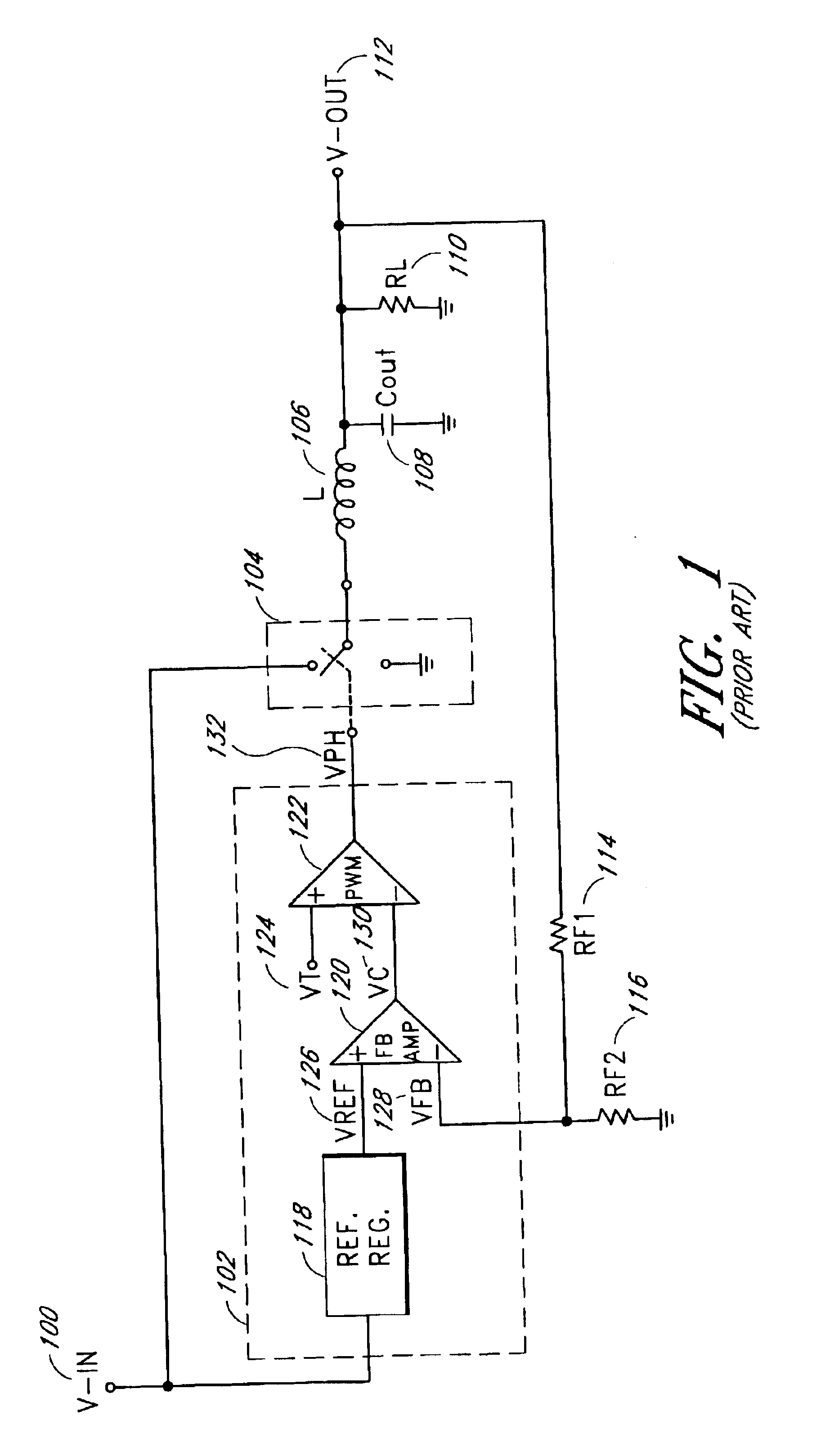
[0041]FIG. 1 is a schematic diagram of a typical switching converter. A voltage source (V-IN) 100 is provided to a controller 102 and to a switch 104 to establish an output voltage (V-OUT) 112. The controller 102 includes a reference regulator (REF. REG.) 118, a feedback amplifier (FB AMP) 120 and a PWM circuit 122.

[0042]The reference regulator 118 accepts an input from the voltage source 100 and generates a reference voltage (VREF) 126. The feedback amplifier 120 compares the reference voltage 126 with a feedback voltage (VFB) 128 and generates a control voltage (VC) 130. The PWM circuit 122 generates a rectangular wave voltage (VPH) 132 based on the control voltage 130 and a triangular wave voltage (VT) 124.

[0043]The rectangular wave voltage 132 controls the operation of the switch 104 which alternately connects the input terminal of an inductor 106 to the voltage source 100 and to ground. The output terminal of the inductor 106 is coupled to the output voltage 112. An output capa...


PUM


Abstract

A plurality of single-phase synchronizing converter automatically synchronize on a peer-to-peer basis. Each synchronizing converter is configured as a DC-to-DC converter. The synchronizing converters operate in parallel as a multi-phase converter. A common bus between the synchronizing converters includes a sync line and a common phase control line. Proper phasing automatically occurs when power is applied, and the phasing changes automatically as converters are added or removed. When the system powers up, the converters arbitrate for phase position. The phasing positions are random, but the phasing is relatively symmetrical regardless of the number of phases. In one embodiment, a hot-swappable converter module can be plugged into any location of a parallel multiphase bus to produce a common output voltage. When an additional module is plugged in, the converters readjust their phases to maintain phase symmetry. In one embodiment, each module shares a substantially equal portion of the output load.

Description

RELATED APPLICATION[0001]This application claims the benefit of priority under 35 U.S.C. § 119(e) from U.S. Provisional Patent Application No. 60 / 392,930 filed on Jun. 28, 2002, the entire contents of which is hereby incorporated by reference.BACKGROUND OF THE INVENTION[0002]1. Field of the Invention[0003]This present invention relates generally to a power conversion circuit and more particularly to a multiphase switching power converter.[0004]2. Description of the Related Art[0005]A typical power conversion circuit (e.g., a switching power converter) receives an input voltage and an input current and modifies the input voltage, the input current or both the input voltage and the input current to produce an output voltage and an output current. For example, a DC-to-DC converter receives input power from a DC voltage source at one voltage level and outputs a desired DC output voltage (typically, a regulated DC output voltage) at another level. A converter that includes a feedback loo...

Claims


Application Information

Patent Timeline
Patent Type & Authority Patents(United States)
IPC IPC(8): G05F1/40H02M3/158
CPCH02M3/1584
Inventor BROOKS, STEVEN W.PICKLE, PAUL
Owner MICROSEMI CORP ANALOG MIXED SIGNAL GRP LTD
Why Eureka
Try Eureka