Counter

a counter and counter technology, applied in the field of counters, can solve the problems of user premature discarding of mdi, affecting the effectiveness of the mdi, and being potentially dangerous

Inactive Publication Date: 2015-08-25
EURO-CELTIQUE SA
View PDF419 Cites 1 Cited by
  • Summary
  • Abstract
  • Description
  • Claims
  • Application Information

AI Technical Summary

Benefits of technology

[0019]In preferred embodiments the first engagement means is connected to, or integral with, the first ring member. This allows for a reduction in the number of components that are movable relative to one another. For practical purposes, however, the first engagement means and first ring member could be manufactured separately and then assembled. Preferably the first engagement means comprises an arm. Particularly preferably the first engagement means comprises an arm having a slot and a contact end member, and in especially preferred embodiments two, three or four arms (e.g. four arms) each having a slot and a contact end member are provided. The contact end is preferably an upwardly extending component that contacts (e.g. rides over) the deflector.
[0022]In preferred embodiments, the counter also comprises a third ring member being coaxially arranged about the common axis of the first and second ring members. Also, the deflector is preferably connected to, or integral with the third ring member. Preferably the third ring member is fixed in use to prevent rotation of the third ring member. Preferably, the third ring member also comprises a limiting mechanism to limit free rotation of the second ring member relative to the third ring member about the common axis. This prevents over-rotation of the second ring member, which would indicate an incorrect number of remaining doses.
[0025]Furthermore, the third ring member preferably comprises one or more locating recesses disposed in an upper circumferential surface for engaging with correspondingly-shaped protrusions in a housing or container for preventing free rotation of the third ring member.

Problems solved by technology

As medicament containers are typically made of an opaque material such as aluminium, and may be housed entirely within a delivery device, it is generally not possible for a user to gauge effectively how many doses of medicament remain therein.
This may result in a user prematurely discarding a MDI still containing doses of medicament or worse using the MDI beyond its recommended lifetime.
Neither situation is desirable—the former is wasteful while the latter is potentially dangerous.
Users sometimes shake MDIs to try to obtain a measure of whether any medicament is present therein, but this only provides a very crude qualitative measure of the container contents.
It would not, for example, enable a user to distinguish between a container comprising enough medicament and propellant to form a dose and one comprising a quantity of medicament and propellant that is less than that needed to fill the metering valve.
In other words, there is a risk that users overestimate the amount of medicament present in a container and mistakenly conclude that there is sufficient medicament remaining for another dose when in fact there is not.
Additionally a user may not be provided with sufficient warning to obtain a replacement medicament container prior to the one in use running out.
In particular it has proven difficult to provide dose counters that reliably “count” the release of medicament doses from containers.
The difficulty encountered is that a relatively small movement, typically of the metering valve stem, needs to be detected and translated into a count.
This difficulty is exacerbated by the fact that manufacturing tolerances in the length of medicament containers means they do not have a consistent length.
At the same time, it is highly undesirable for any movements to not be counted since this will lead to the counter indicating a higher number of doses remaining than is actually the case.
Moreover there is also regulatory pressure to minimise the number of false counts.

Method used


Image

  • Counter
  • Counter
  • Counter

Examples


Embodiment Construction

Dispenser

[0057]To explain the invention, a brief overview of some features and operating principles of exemplary dispensers is initially provided. As used herein the term “dispenser” is intended to mean any device having a body suitable to receive a container holding a product and which has a mechanism to dispense the product from the container upon actuation.

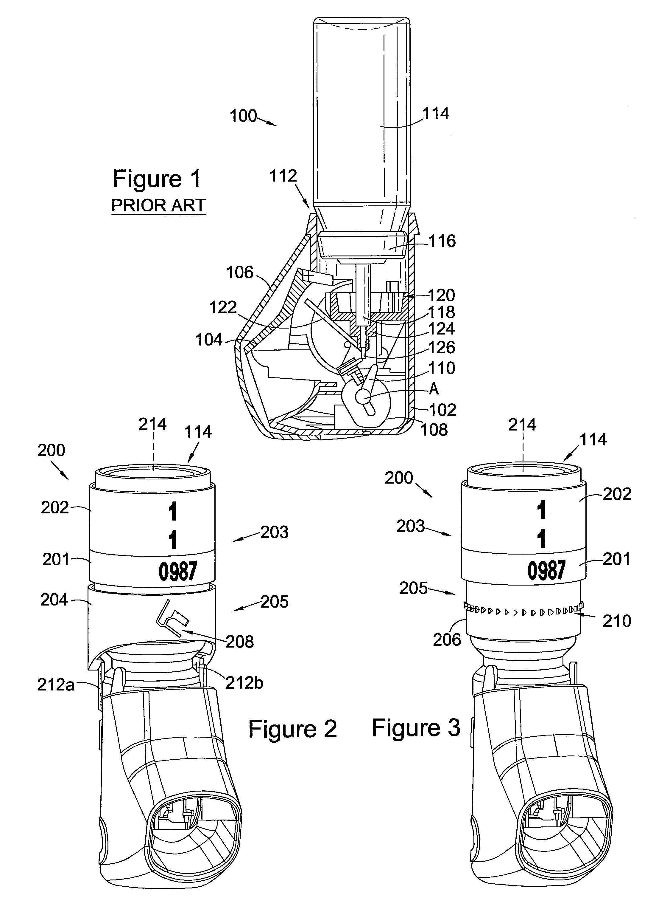
[0058]FIG. 1 shows in partial cross section an example of a breath-actuated, kink valve dispenser. The dispenser 100 comprises a body 102 with a mouthpiece 104 and a pivotable mouthpiece cover 106. The mouthpiece cover is pivotable about an axis, A, low in the body and carried on a cam arrangement comprising two cam lobes (only one cam lobe 108 is shown), together with a central finger 110. The body has an opening 112 for receiving a medicament container 114. The container may be held fixedly in place at the upper end of the body, at a location where the body extends completely around a metering valve assembly of the container ...


PUM


Abstract

A counter containing: a first ring member having first indicia and a second ring member having second indicia, each of the first and second ring members being rotatable in increments about a common axis, one or both of the first and second indicia indicating a count; a drive mechanism for rotating the first ring member; and a coupling mechanism for releasably coupling the first ring member to the second ring member, to allow the first and second ring members to rotate cooperatively when coupled and to allow independent rotating of the first ring member when not coupled; wherein the coupling mechanism contains first and second engagement structures, the first engagement structures being movable radially outwardly and radially inwardly relative to the axis.

Description

[0001]This application is the U.S. national phase of International Application No. PCT / GB2010 / 050404, filed 10 Mar. 2010, which designated the U.S. and claims priority to GB Application No. 0904040.3, filed 10 Mar. 2009, the entire contents of each of which are hereby incorporated by reference.FIELD OF THE INVENTION[0002]This invention generally relates to counters and in particular to counters for use with dispensers and to dispensers comprising said counters. More particularly the present invention relates to counters for use with metered-dose dispensers, such as metered-dose inhalers (MDIs).BACKGROUND OF THE INVENTION[0003]Counters are useful in a wide variety of applications, and are especially important in the field of medical dispensers where an accurate determination of the number of doses of medicament remaining in a medicament container might otherwise be difficult to obtain. An example of such a medical dispenser is a metered-dose inhaler.[0004]Metered-dose inhalers (MDIs)...

Claims


Application Information

Patent Timeline
Patent Type & Authority Patents(United States)
IPC IPC(8): A61M15/00G06M1/16G06M1/24G06M1/00
CPCA61M15/0065A61M15/009A61M15/0073G06M1/163G06M1/248A61M15/0075G06M1/041G06M1/083G06M1/241
Inventor BACON, RAYMONDMCDERMENT, IAIN GRIERSON
Owner EURO-CELTIQUE SA
Why Eureka
Try Eureka