Motorized automate/manual push button system

a push button and automatic technology, applied in the field of flushing machines, can solve the problems of failure to operate the automatic operation mechanism, the structural design of the automated operation mechanism is different from that of the manual operation mechanism, and the maintenance cost of the automated operation mechanism is higher than that of the conventional manual operation mechanism, so as to achieve the effect of eliminating odors, eliminating odors, and ensuring the effect of water quality

Inactive Publication Date: 2015-08-25
ADVANCED MODERN TECH
View PDF12 Cites 4 Cited by
  • Summary
  • Abstract
  • Description
  • Claims
  • Application Information

AI Technical Summary

Benefits of technology

[0017]Another advantage of the invention is to provide a fully programmable automatic flush control device for the flush apparatus. Accordingly, the flush intervals can be programmed to flush once every 1, 2, 4, 8, 12, or 24 hours.
[0018]Another advantage of the invention is to provide a motorized automate / manual push button system which is designed to be used in conjunction with a urinal deodorizer / screen to provide for ultimate water efficiency while eliminating odors.
[0019]Another advantage of the invention is to provide a motorized automate / manual push button system which is a non-sensor device, such that the flushing operation is completed exclusive of a presence of a user.
[0020]Another advantage of the invention is to provide a motorized automate / manual push button system which is easy programming and installation.
[0021]Another advantage of the invention is to provide a motorized automate / manual push button system which has a manual flush override option using special key.
[0022]Another object of the present invention is to provide a motorized automate / manual push button system for a flush apparatus, which is a driving mechanism adapted for incorporating with the flush apparatus to selectively actuate the flush apparatus automatically by a motorized device in responsive to a presence of a user and manually by an actuation of a push button.

Problems solved by technology

However, the automated operation mechanism has several common drawbacks.
It is one of the common problems to cause a failure of operation of the automated operation mechanism.
Thus, the maintenance cost of the automated operation mechanism is higher than that of the conventional manual operation mechanism.
In addition, the structural design of the automated operation mechanism is different from that of the manual operation mechanism.
In other words, when the flush apparatus is incorporated with the automated operation mechanism, the flush apparatus will lose the mechanical-manual operated feature.
Therefore, there is no alternative to flush the sanitary system when the automated operation mechanism has failed to operate.
In order to install the automated operation mechanism into the conventional flush apparatus, the manual operation mechanism of the flush apparatus must be totally removed, which is a waste of resources in order to incorporate with the automated operation mechanism.
However, the cartridge must be replaced often and the replacement of the cartridge is relatively expensive.
As a result, the maintenance cost of the waterless flush apparatus will be higher than the conventional flush apparatus.

Method used


Image

  • Motorized automate/manual push button system
  • Motorized automate/manual push button system
  • Motorized automate/manual push button system

Examples


second embodiment

[0102] the driving mechanism comprises an actuation housing 50′, an automated actuation unit 60′, a manual actuation unit 70′, and power charging arrangement 40′.

[0103]The actuation housing 50′, having an actuation channel 501′, is supported by the valve body 10. Accordingly, the actuation housing 50′ is mounted at the valve body 10 at a position that the actuation housing 50′ is positioned adjacent to the valve body 10. As shown in FIG. 8, the actuation housing 50′ comprises a housing body 51′ defining the actuation channel 501′ at a bottom portion thereof and a tubular mounting element 52′ mounting at said valve body to align the actuation channel 501′ with the diaphragm shaft 22′. Accordingly, the actuation channel 501′ is transversely extended to communicate with the bottom portion of the diaphragm shaft 22′.

[0104]The automated actuation unit 60′ is received in the housing body 51′ at a position above the actuation channel 501′, wherein the automated actuation unit 60′ comprises...

third embodiment

[0122] the driving mechanism can be formed as a flush water volume control arrangement for controlling flush water volume during a flushing operation. Accordingly, the first pusher member 621A is supported transversely for moving toward the first position 221′ of the diaphragm shaft 22′ to complete the flushing operation with a relatively high volume of water, as shown in FIG. 12. The second pusher member 622A is supported transversely for moving toward the second position 222′ of the diaphragm shaft 22′ to complete the flushing operation with a relatively low volume of water, as shown in FIG. 13.

[0123]In other words, the pushing end 620A of the first pusher member 621A is higher than the pushing end 620A of the second pusher member 622A such that the first position 221′ of the diaphragm shaft 22′ being pushed by the first pusher member 621A is positioned higher than the second position 222′ of the diaphragm shaft 22′ being pushed by the second pusher member 622′.

[0124]It is worth t...

fifth embodiment

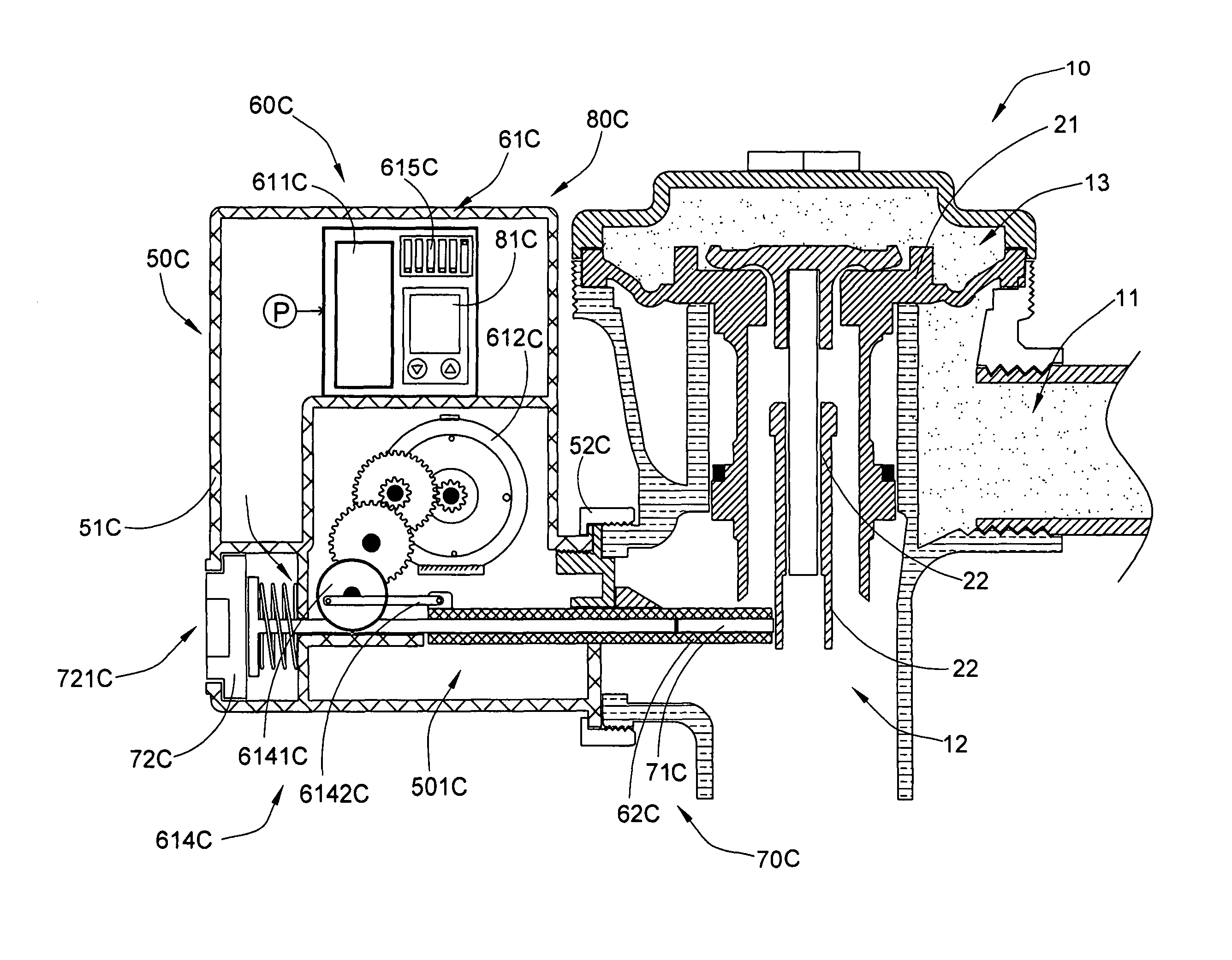
[0155] the driving mechanism comprises an actuation housing 50C and an automated actuation unit 60C.

[0156]The actuation housing 50C, having an actuation channel 501C, is supported by the valve body 10. Accordingly, the actuation housing 50C is mounted at the valve body 10 at a position that the actuation housing 50C is positioned adjacent to the valve body 10. As shown in FIG. 20, the actuation housing 50C comprises a housing body 51C defining the actuation channel 501C at a bottom portion thereof and a tubular mounting element 52C mounting at the valve body 10 to align the actuation channel 501C with the diaphragm shaft 22. Accordingly, the actuation channel 501C is transversely extended to communicate with the bottom portion of the diaphragm shaft 22.

[0157]The automated actuation unit 60C is received in the housing body 51C at a position above the actuation channel 501C, wherein the automated actuation unit 60C comprises a motorized unit 61C received in the housing body 51C of the...


PUM

PropertyMeasurementUnit
rotating angleaaaaaaaaaa
pushing forceaaaaaaaaaa
poweraaaaaaaaaa

Abstract

A driving mechanism of a flush apparatus includes a motorized unit supported by a valve body, a plunger arm driven by the motorized unit for operating the valve body between a sealed position to an unsealed position, and a timer module operatively linked to the motorized unit to set a flush interval for enabling the flushing operation to be completed once every flush interval. The driving mechanism converts the flush apparatus into water efficient fixture by controlling the amount of daily flushes for ultimate water efficiency.

Description

CROSS REFERENCE OF RELATED APPLICATION[0001]This is a Continuation-In-Part application that claims the benefit of priority under 35 U.S.C. §119 to a non-provisional application, application Ser. No. 13 / 385,857, filed Mar. 8, 2012, which is a Continuation-In-Part application that claims the benefit of priority under 35 USC119(e) of earlier filed non-provisional application having an application Ser. No. 13 / 136,645 and a filing date Aug. 5, 2011, which is a Continuation application having an application Ser. No. 12 / 220,231 and a filing date of Jul. 22, 2008.NOTICE OF COPYRIGHT[0002]A portion of the disclosure of this patent document contains material which is subject to copyright protection. The copyright owner has no objection to any reproduction by anyone of the patent disclosure, as it appears in the United States Patent and Trademark Office patent files or records, but otherwise reserves all copyright rights whatsoever.BACKGROUND OF THE PRESENT INVENTION[0003]1. Field of Invention...

Claims


Application Information

Patent Timeline
Patent Type & Authority Patents(United States)
IPC IPC(8): E03D5/10F16K31/04F16K31/05F16K31/40F16K31/385E03D3/06E03D5/12
CPCE03D5/10E03D3/06E03D5/12F16K31/04F16K31/05F16K31/3855F16K31/404Y10T29/4943Y10T29/49826
Inventor MAERCOVICH, JORGE
Owner ADVANCED MODERN TECH
Why Eureka
Try Eureka