Optical apparatus and operating method thereof

a technology of optical equipment and operating method, applied in the field of optical detection, can solve the problems of affecting the overall optical scanning detection efficiency, unable to detect, and taking longer time, so as to enhance the overall scanning efficiency, reduce human burden, and increase the scanned area

Active Publication Date: 2015-09-01
CRYSTALVUE MEDICAL
View PDF3 Cites 0 Cited by
  • Summary
  • Abstract
  • Description
  • Claims
  • Application Information

AI Technical Summary

Benefits of technology

[0012]Compared to the prior arts, the optical apparatus and operating method thereof in the invention will perform the rotation scanning through the integration of the rotation axis and the optical probe; therefore, the scanned area can be largely increased to enhance the overall scanning efficiency. And, 2-D area detection can be provided by 1-D direction scanning of the rotation mirror of the optical apparatus cooperating with the rotation of the rotation axis. Furthermore, the optical apparatus of the invention can include a platform of 6-degrees of freedom, and the platform can cooperate with a control apparatus similar to a joystick (or a mouse, a keyboard), a display, a micro-camera, and a sensor to perform the observation, positioning, and detection of the body parts of the patient, therefore, the human burden can be effectively reduced.

Problems solved by technology

However, once the design of the rotation mirror is used to detect the non-circumference large-area region S (e.g., the skin), because of the limitation of the rotation angle of the rotation mirror, the scanned region of the incident lines L1˜L3 provided by the rotation mirror may fail to cover all regions to be detected on the large-area region S, some regions to be detected will not be detected.
However, each of the small regions M1˜M6 will be limited by the rotation angle of the rotation mirror RM, therefore, it takes longer time to finish the scanning of the entire non-circumference large-area region, and the overall optical scanning detection efficiency will be seriously affected.

Method used


Image

  • Optical apparatus and operating method thereof
  • Optical apparatus and operating method thereof
  • Optical apparatus and operating method thereof

Examples


first embodiment

[0023]the invention is an optical apparatus. hi this embodiment, the optical apparatus can be a skin optical image detection apparatus used to detect the non-circumference large-area region similar to the skin, but not limited to this case. In fact, the optical apparatus can be the optical coherence tomography or other similar equipments without specific limitations.

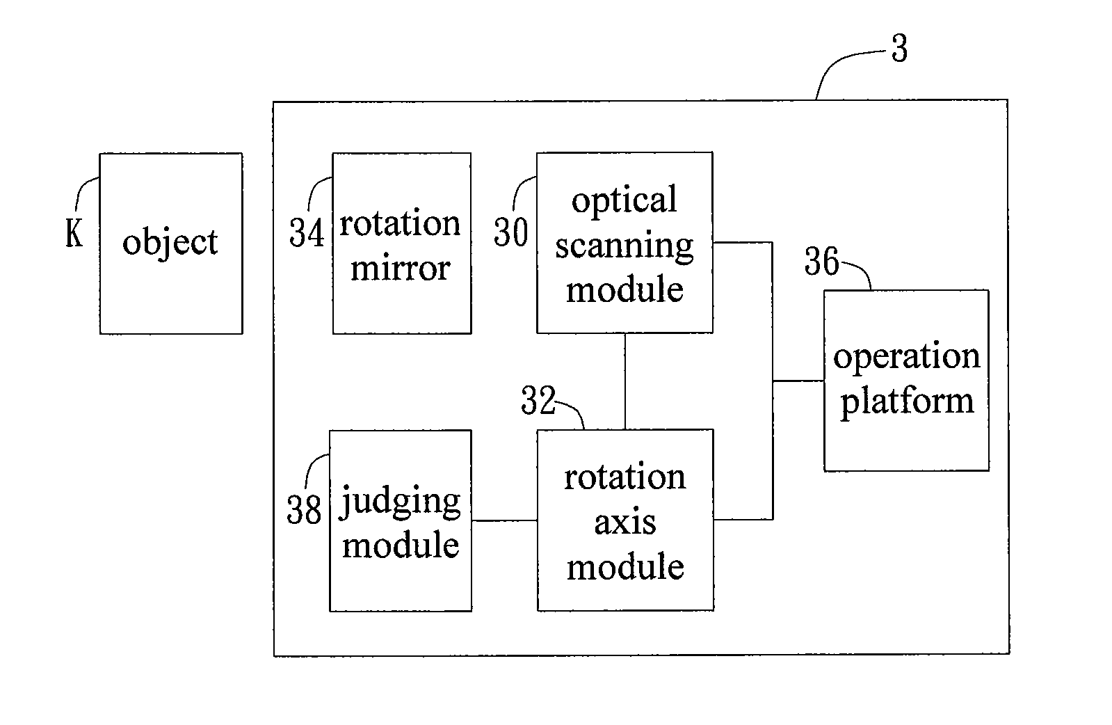
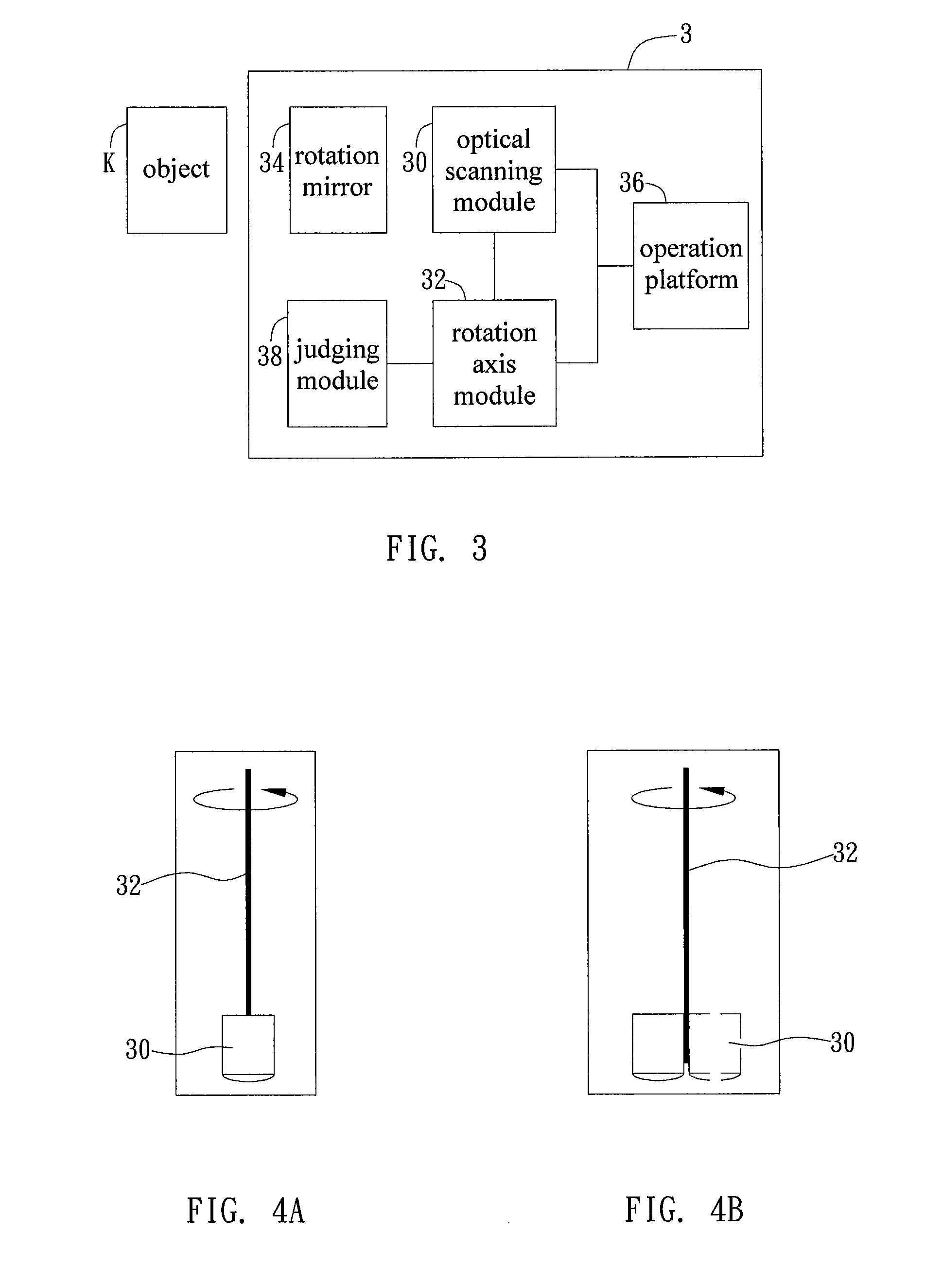
[0024]Please refer to FIG. 3. FIG. 3 illustrates the functional block diagram of the optical apparatus in this embodiment. As shown in FIG. 3, the optical apparatus 3 is used to perform an optical coherence tomography detection process on an object K. The optical apparatus 3 includes an optical scanning module 30, a rotation axis module 32, a rotation mirror 34, an operation platform 36, and a judging module 38. Wherein, the rotation mirror 34 is disposed between the optical scanning module 30 and the object K; the judging module 38 is coupled to the rotation axis module 32; the optical scanning module 30 is integrated w...

second embodiment

[0032]the invention is an optical apparatus operating method. In this embodiment, the optical apparatus includes an optical scanning module and a rotation axis module, and the rotation axis module is integrated with the optical scanning module. Please refer to FIG. 7. FIG. 7 illustrates a flowchart of the optical apparatus operating method in this embodiment.

[0033]As shown in FIG. 7, at first, the method performs the step S10 to judge whether the object and a detected region and a positioning point on the object are correct. In fact, the detected region on the object can be a non-circumference large-area region similar to the skin, but not limited to this case.

[0034]If the judgment of the step S10 is YES, the method will perform the step S12, when the rotation axis module rotates, the rotation axis module will bring the optical scanning module to perform the rotation scanning process on the object. In fact, the rotation axis module can bring the optical scanning module to perform th...


PUM


Abstract

An optical apparatus is disclosed. The optical apparatus includes an optical scanning module and a rotation axis module. The optical scanning module is used to provide an optical signal for optical tomography. The rotation axis module and the optical scanning module are integrated. When the rotation axis module rotates, the rotation axis module makes the optical scanning module to perform a rotation scanning process to an object.

Description

BACKGROUND OF THE INVENTION[0001]1 . Field of the Invention[0002]The invention relates to optical detection, in particular, to an optical apparatus and operating method thereof capable of effectively enhancing the overall optical scanning detection efficiency through the disposition of the rotation axis.[0003]2 . Description of the Prior Art[0004]In recent years, with the continuous development of the optical detection technology, several kinds of optical detection equipments have been developed. For example, the optical coherence tomography can be used as a fundus optical image apparatus to provide a cross-sectional image of the retina, and the optical coherence tomography uses the rotation of the rotation mirror to reflect the detected light to different directions to detect different locations of the fundus.[0005]As shown in FIG. 1, because the size of the eye is relatively small and the fundus region R of the retina can be regarded similar to the circumference, the scanned regio...

Claims


Application Information

Patent Timeline
Patent Type & Authority Patents(United States)
IPC IPC(8): G01B9/02A61B3/10A61B5/00
CPCA61B5/0066A61B3/102
Inventor YEN, MENG-SHINWANG, WILLIAMCHOU, CHUNG-CHENG
Owner CRYSTALVUE MEDICAL
Why Eureka
Try Eureka