Method for Gridding and Quality Control of Polymer Arrays

Inactive Publication Date: 2007-07-05
AFFYMETRIX INC
View PDF23 Cites 0 Cited by
  • Summary
  • Abstract
  • Description
  • Claims
  • Application Information

AI Technical Summary

Benefits of technology

[0012] The extent of hybridization of the target molecule to the known probe sequences can be correlated with the quality of the microarray as a whole or can further be used to align a grid onto the microarray surface for the purpose of identifying probes at certain locations on the array. The use of known probe sequences provides useful information on design verification, synthesis verification, gridding and signal intensity and in certain circumstances without having to scan the entire array.
[0017] According to an additional embodiment of the invention, a method for gridding or quality control of an oligonucleotide array is provided. The array has a plurality of quality control blocks surrounded at the four corners of each quality control block with first checkerboard features. The terms “blocks” and “features” refers to the probe sequences on the array at defined regions. According to an aspect of the method, a quality control block is provided at the center of the array and second checkerboard features are provided samples that are capable of hybridizing or binding to the first checkerboard features do not hybridize or bind to the second checkerboard features and vice versa. The center control blocks and the second checkerboard features are imaged to allow for gridding of the array and determining whether the probes in the quality control blocks have been accurately synthesized. The use of distinct checkerboard features for gridding of the array advantageously allows for an increased scan area of the array for gridding purposes without having other checkerboard patterns not associate with gridding interfering with the gridding algorithm used by the software.

Problems solved by technology

For example, errors may occur if a chemical is not properly added, a wash step is skipped, concentrations are not correct, timing is incorrect, the wrong mask is utilized, the correct mask is misaligned, and the like.
It is often very difficult to detect any errors at all and many of the errors only affect a small limited number of probes on the chip.

Method used


Image

  • Method for Gridding and Quality Control of Polymer Arrays

Examples


Embodiment Construction

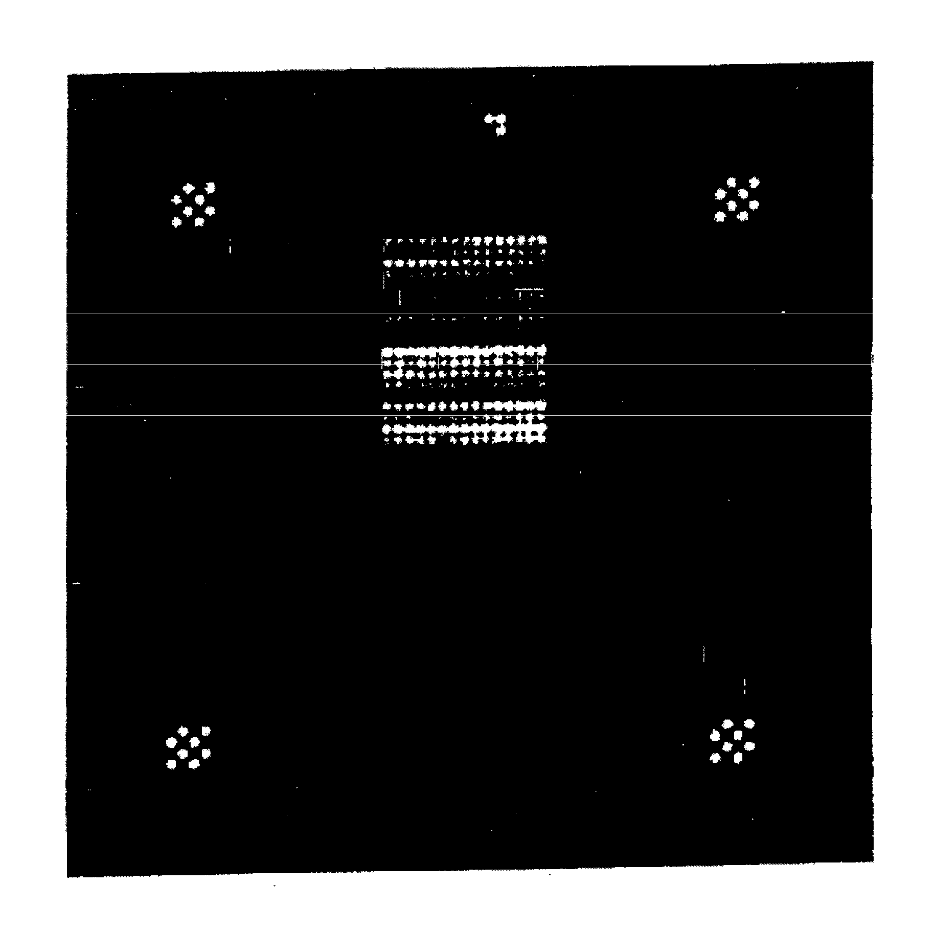
[0018] Embodiments of the present invention are directed to the use of two or more sets of control probes located at predefined regions of the array in selected patterns. The methods of the present invention are useful in gridding or aligning the array and in determining the extent of hybridization to the array given variations in array manufacture.

[0019] According to one embodiment of the present invention, control probes are located on the array at predefined regions and can be advantageously scanned without having to scan the entire array which reduces time spent on quality control analysis. A further embodiment of the invention includes separate sets of control probes which are different from each other, such that hybridization to one set of probes provides different quality control information from hybridization to a different set of control probes. According to one aspect, different sets of control probes are located at different predefined regions on the array. In this manne...


PUM

PropertyMeasurementUnit
Densityaaaaaaaaaa

Abstract

Methods of using a plurality of control probes for gridding of a nucleic acid array and for quality control purposes are disclosed.

Description

FIELD OF THE INVENTION [0001] The present invention relates to methods of making microarrays having known probe sequences at predefined locations on a microarray substrate where the probe sequences can be scanned for purposes of gridding the array and / or quality control. The present invention also relates to the microarrays themselves having probe sequences at predefined regions on the array that are used for gridding or quality control. BACKGROUND OF THE INVENTION [0002] A variety of systems are known for synthesizing or depositing dense arrays of biological materials, sometimes referred to as probes, on a substrate or support. Labeled targets in hybridized probe-target pairs may be detected using various commercial devices, referred to for convenience hereafter as scanners. Scanners image the targets by detecting fluorescent or other emissions from the labels. Data representing the detected emissions are stored in a memory device for processing. The processed images may be present...

Claims


Application Information

Patent Timeline
IPC IPC(8): C12Q1/68
CPCC12Q1/6837C12Q2545/101
Inventor CICCOLELLA, PAUL C.ESTRADA, RYAN
Owner AFFYMETRIX INC
Why Eureka
Try Eureka