Image processing unit, image processing method, and image processing program

a technology of image processing and image synthesis, applied in the field of image processing units, image processing methods and image processing programs, can solve the problems of inability to detect the inability to accurately synthesize continuously captured images, and inability to detect motion of a subject, etc., to achieve accurate synthesizing continuous captured images

Active Publication Date: 2013-05-09
RICOH KK
View PDF2 Cites 6 Cited by
  • Summary
  • Abstract
  • Description
  • Claims
  • Application Information

AI Technical Summary

Benefits of technology

The invention provides an image processing unit, method, and program that can accurately mix capturing frames without causing image crashes. This is done by adjusting a threshold for selecting which frames to mix based on the output of a reference frame. This approach allows for more efficient and effective image correction.

Problems solved by technology

Image synthesis without subject's motion taken into account results in increasing blurs and noise in the image.
There is a problem with determining an image synthesis using a predetermined threshold as in the image processing method disclosed in Reference 2.
However, the large threshold set for the light portion is too large for the dark portion of a subject image, making it impossible to detect motion of a subject in the dark portion and leading to erroneous determination on the image synthesis.
Because of this, the images are erroneously determined to be suitable for image synthesis, resulting in generation of an image with profiles R along the motion of the subject X or a ghost Z.
Accordingly, the image blocks corresponding to the bright area are not synthesized and the averaging of noise is not achieved by the image synthesis so that noise is conspicuous in the locally bright area.
As described above, using a fixed threshold, suitability of images for image synthesis cannot be accurately determined and as a result, the image synthesis is not properly done.
This induces occurrence of ghosts or distinctive noise in images and causes image crash.

Method used


Image

  • Image processing unit, image processing method, and image processing program
  • Image processing unit, image processing method, and image processing program
  • Image processing unit, image processing method, and image processing program

Examples


first embodiment

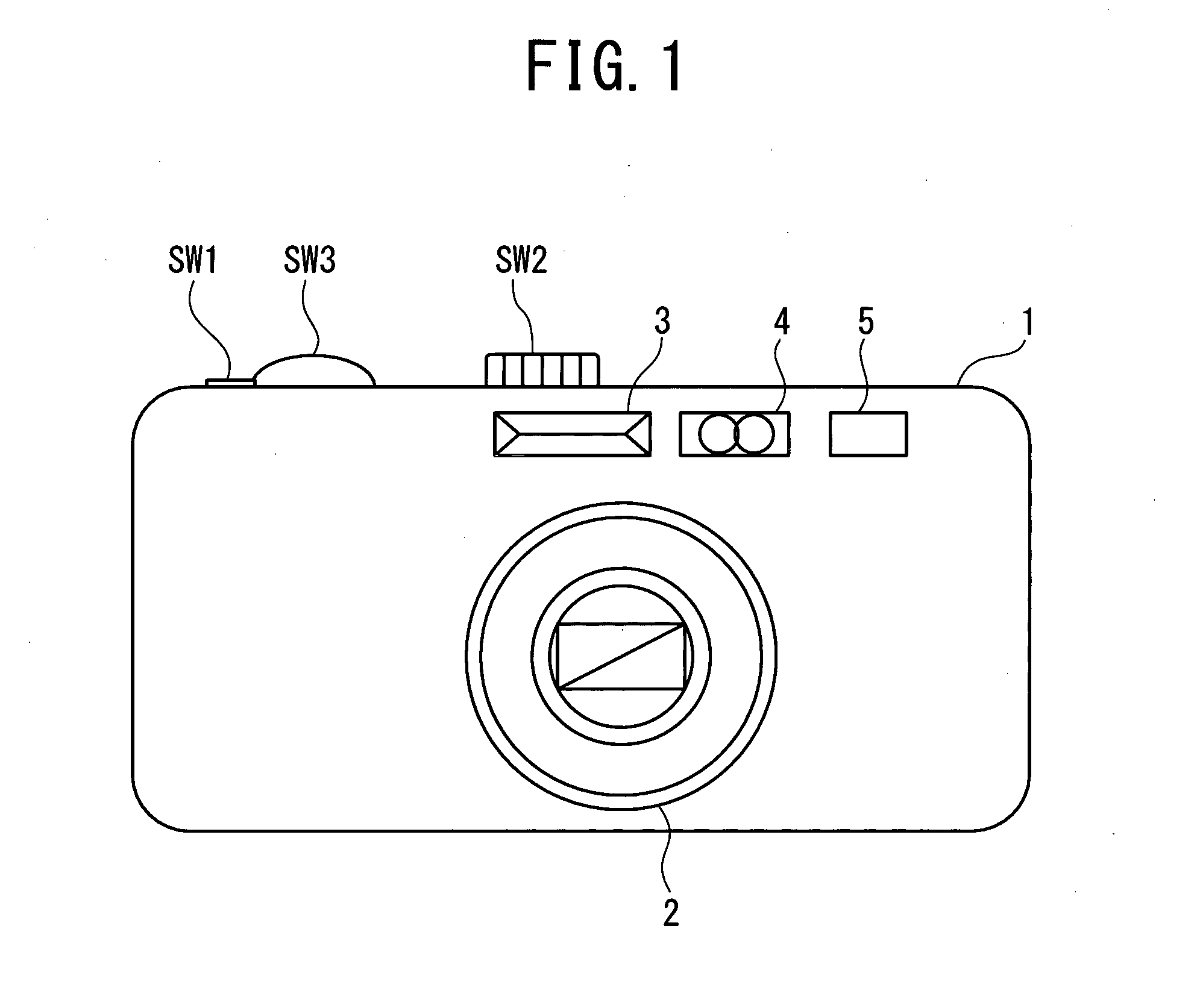
[0030]FIG. 1 is a front view of an exemplary imaging device comprising the image processing unit according to a first embodiment. In FIG. 1 an imaging device 1 comprises a lens barrel unit 2 including a zoom lens and a focus lens, a stroboscopic unit 3, a ranging unit 4 to measure a distance to a subject, and an optical finder 5. On a front face a shutter button SW1, a mode dial SW2 to select a shooting mode, a jog dial switch SW3 are provided. By manipulation to the shutter button SW1, an image of a subject is captured via various lenses of the lens barrel unit 2, taken into a not-shown image sensor and stored as image data in a not-shown memory unit. Multiple images can be continuously stored in the memory unit by a single shooting operation. For example, four items of continuous image data can be stored by a single manipulation to the shutter button SW1.

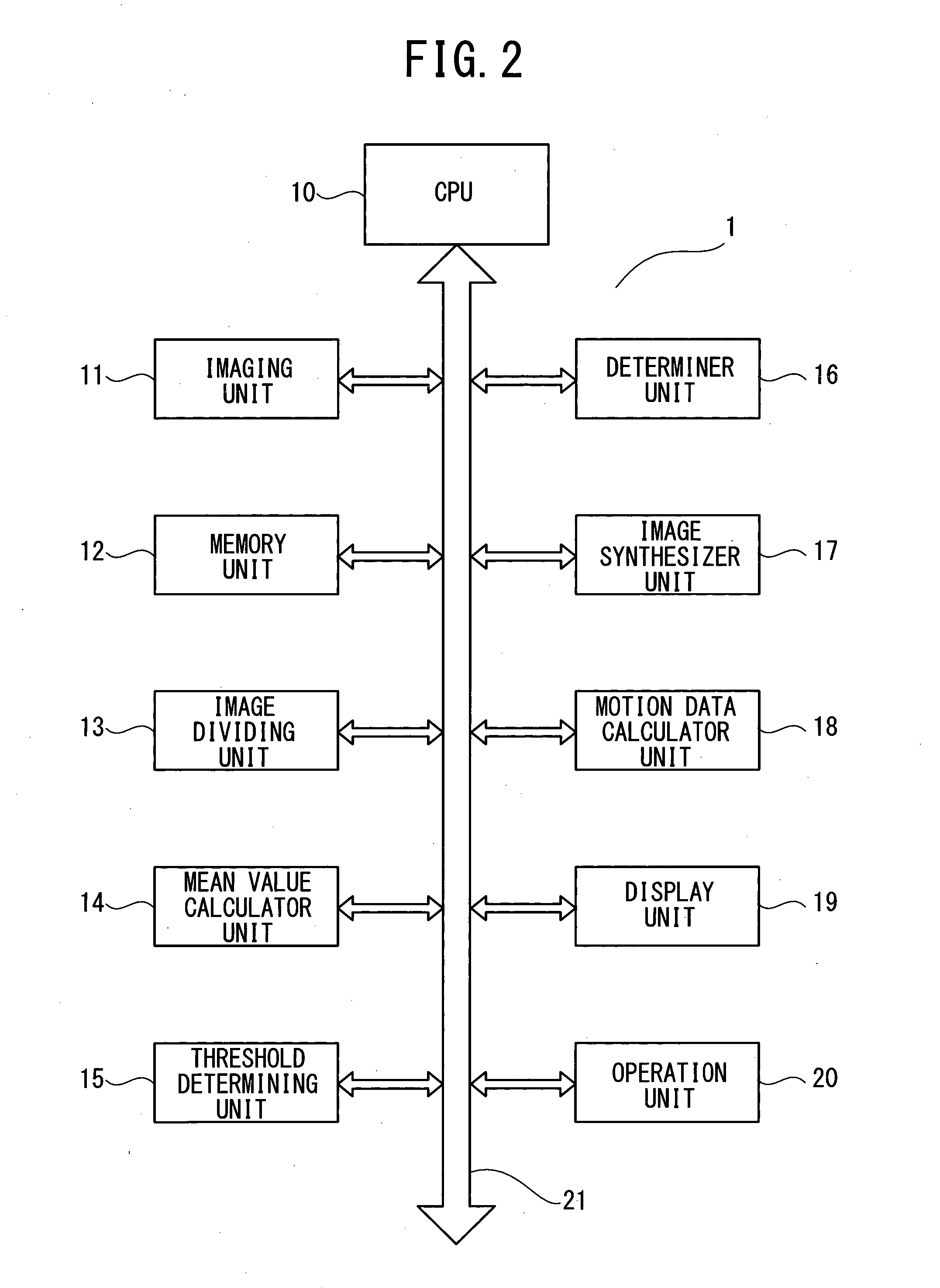
[0031]Next, an example of function blocks of the imaging device 1 according to the present embodiment is described, referring to...

second embodiment

[0045]Next, an example of image processing executed by the image processing unit according to the first embodiment will be described with reference to a flowchart in FIG. 6.

[0046]In step S1 the imaging unit 11 continuously captures images of a subject at the same parameter setting (aperture diaphragm, exposure time, ISO sensitivity, angle of view and else), and the captured images are stored in the memory unit 12. Next, in step S2 the motion data calculator unit 18 calculates motion data for determining a relation between a reference image and a comparative image stored in the memory unit 12 and the CPU 10 aligns positions of the reference image and the comparative image based on the motion data. The position alignment in step S2 is to correct displacement of the comparative image from the reference image.

[0047]In step S3 a determination is made on whether or not the reference image and the comparative image are suitable for the image synthesis. In step S4 the number of images synth...

third embodiment

[0056]Another example of the image synthesis determination in step S3 is described in detail with reference to a flowchart in FIG. 8. The same operations as those in FIG. 7 are given the same step numbers in FIG. 8. First, in step S10 the image dividing unit 13 divides each of a reference image and a first comparative image into image blocks of a predetermined size. The mean value calculator unit 14 calculates a mean value of brightness of a k-th image block of the reference image to determine a threshold for determining execution / non-execution of the image synthesis in step S21.

[0057]The threshold determining unit 15 determines a threshold for determining whether images in the image block are suitable for image synthesis based on the calculated the mean brightness value in step S21, referring to the threshold table stored in the work memory. The threshold table contains a group of data as difference values of representative mean brightness values associated with thresholds based on...


PUM


Abstract

An image processing unit includes a memory unit in which continuously captured images including a reference image and a comparative image are stored, an image dividing unit to divide the reference image and the comparative image into image blocks of a predetermined size, a mean value calculator unit to calculate a mean value of pixel outputs in each image block of each of the reference and comparative images, a threshold determining unit to determine a threshold according to a mean value of pixel outputs of an image block of the reference image, and a determiner unit to compare the threshold with a difference value of the mean values of the pixel outputs in the image blocks of the reference and comparative images to be synthesized and determine whether the image blocks of the reference and comparative images are suitable for image synthesis based on a result of the comparison.

Description

CROSS REFERENCE TO RELATED APPLICATION[0001]The present application is based on and claims priority from Japanese Patent Application No. 2010-155869, filed on Jul. 8, 2010, the disclosure of which is hereby incorporated by reference in its entirety.TECHNICAL FIELD[0002]The present invention relates to an image processing unit, an image processing method and an image processing program which can correct blurs and noise in an image due to camera shakes or else with high precision without crashing the image.BACKGROUND ART[0003]In the recent years, by making use of the speed-up operation of an image sensor such as CMOS, digital cameras with various functions have been developed. For example, there is one capable of continuously storing five images or more per second or one capable of high-speed video shooting at 1000 fps or more. It is known that such digital cameras include an image processing unit to synthesize continuously shot images for the purpose of removing from images blurs cau...

Claims


Application Information

Patent Timeline
Patent Type & Authority Applications(United States)
IPC IPC(8): G06K9/68
CPCH04N5/23277G06T5/50G06K9/68G06T2207/20021G06T7/2013G06T7/223H04N23/6845
Inventor HOHJOH, DAISUKE
Owner RICOH KK
Why Eureka
Try Eureka