Check patentability & draft patents in minutes with Patsnap Eureka AI!

Liquid crystal display apparatus

a technology of liquid crystal display and display device, which is applied in non-linear optics, instruments, optics, etc., can solve the problems of uneven display and easy disconnection of segment electrodes, and achieve the effect of preventing electrode disconnection and increasing electrical resistan

Active Publication Date: 2015-09-01
STANLEY ELECTRIC CO LTD
View PDF9 Cites 0 Cited by
  • Summary
  • Abstract
  • Description
  • Claims
  • Application Information

AI Technical Summary

Benefits of technology

[0011]According to the above described configuration, in a case where the shape and surface area of the upper and lower electrodes need to be made dissimilar, such as in a segment display-type liquid crystal display apparatus, for example, the first electrode provided with the first opening comprising a relatively simple shape can be used as the electrode for which the electrode surface area decreases, and the second electrode provided with the second opening comprising a relatively complex shape can be used as the electrode for which the electrode surface area increases. With this arrangement, it is possible to more readily prevent electrode disconnection and make the apparatus less susceptible to display unevenness caused by increases in electrical resistance.
[0014]With this arrangement, it is possible to control the surface area in the planar view of the respective orientation domains oriented in a plurality of directions inside each of the rectangular regions by the position of each of the first openings, thereby making it possible to freely control the viewing angle dependency.
[0018]With this arrangement, it is possible to prevent electrode disconnection and electrical resistance increase in a segment display-type liquid crystal display apparatus.

Problems solved by technology

Nevertheless, in a segment display-type liquid crystal display apparatus such as described above, the segment electrode (or common electrode) is made into a shape that is almost an outline of the display part, causing segment electrode disconnection to more readily occur.
Further, even if disconnection does not occur, the electrical resistance more readily increases, resulting in the concern that this may cause display unevenness in which the brightness during a bright display differs between each of the plurality of display parts.

Method used


Image

  • Liquid crystal display apparatus
  • Liquid crystal display apparatus
  • Liquid crystal display apparatus

Examples


embodiment 1

[0034]FIG. 1 is a cross-sectional view showing the basic structure of the liquid crystal display apparatus of embodiment 1. This liquid crystal display apparatus comprises a first substrate 11 and a second substrate 12 disposed facing each other, a first electrode 13 provided to the first substrate 11, a second electrode 14 provided to the second substrate 12, and a liquid crystal layer 17 disposed between the first substrate 11 and the second substrate 12, as a basic configuration. For example, the liquid crystal display apparatus of this embodiment is configured so that the region where the electrodes overlap each other forms the characters and designs that the user wants to display. The apparatus is basically capable of displaying only predetermined characters and the like, and is a segment display-type liquid crystal display apparatus wherein generally a region of about 50% or less in terms of the area ratio inside the effective display region contributes to the display of chara...

embodiment 2

[0048]As a structure that achieves the same advantages as those of the above described embodiment 1, each of the second openings can be simply made into an inverted T-shape.

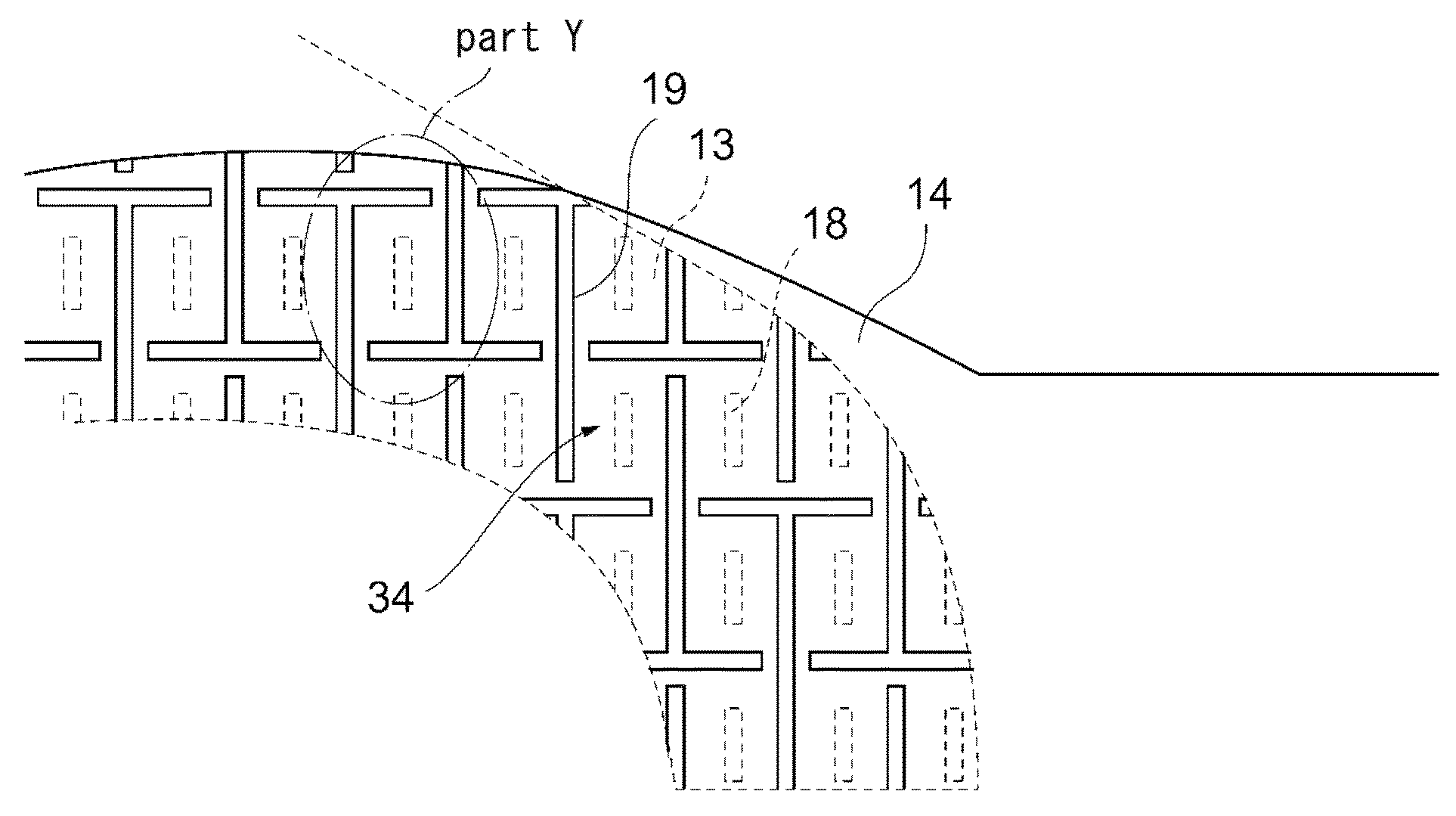
[0049]FIG. 7 is a plan view showing the first electrode and the second electrode of the embodiment 2 superimposed. Note that the overall configuration of the liquid crystal display apparatus is the same as that of embodiment 1 and explanations thereof will be omitted (the same holds true for the embodiments hereafter). As illustrated in FIG. 7, all of the second openings 19 of the second electrode 14 are inverted T-shaped openings and respectively cyclically disposed in the vertical direction and the horizontal direction. At this time, while each of the second openings 19 in adjacent columns comprises an inverted T-shape and is cyclically disposed in the vertical direction, the positions of the center of gravity thereof are shifted substantially one-half pitch per column. On the other hand, the structures of the ...

embodiment 3

[0051]While the embodiment 1 and the embodiment 2 described above indicate cases where four main orientation regions exist and the surface areas of the main orientation regions of each of the vertical and horizontal directions are substantially equal, it is also possible to control viewing angle dependency by narrowing and widening specific main orientation directions.

[0052]FIG. 12A is a figure showing the structure of the first electrode based on simulation analysis. Note that the structures of the second electrode and second opening are the same as those shown in FIG. 11A described above. The first opening of the first electrode shown here comprises a structure wherein the long side extends up to the upper side edge of the rectangular region configured by the second openings of the second electrode in relation to the upward direction. Note that the conditions of simulation analysis are the same as those described above. FIG. 12B is a figure showing the calculation result of the or...


PUM

PropertyMeasurementUnit
thicknessaaaaaaaaaa
thicknessaaaaaaaaaa
dielectric constantaaaaaaaaaa

Abstract

The apparatus comprises a first and a second substrate disposed facing each other, a first electrode comprising first openings provided to the first substrate, a second electrode comprising second openings provided to the second substrate, and a liquid crystal layer disposed between the first and the second substrate. A display part is defined in a region where the first and the second electrode overlap, each of the first openings is formed into a rectangular shape in the planar view, each of the second openings is formed into a rectangular shape or cruciform shape in the planar view, the second electrode comprises rectangular regions cyclically disposed inside the display part in the planar view, the four sides that define each of the rectangular regions respectively contact any portion of the second openings, and each of the first openings is disposed overlapping any of the rectangular sections in the planar view.

Description

BACKGROUND OF THE INVENTION[0001]1. Field of the Invention[0002]The present invention relates to a liquid crystal display apparatus comprising electrodes with openings.[0003]2. Description of the Background Art[0004]As one technique that improves the viewing angle dependency of a liquid crystal display apparatus, there is known a multi-domain orientation technique that provides a plurality of openings (slits) to the respective upper and lower electrodes disposed facing each other and sandwiching a liquid crystal layer therebetween, thereby dividing the orientation domain of the liquid crystal molecules of the liquid crystal layer into a plurality of directions inside a single pixel when voltage is applied to the liquid crystal layer. For example, Japanese Patent No. 4107978 discloses a liquid crystal display apparatus (liquid crystal display device) wherein each opening of an upper electrode and each opening of a lower electrode are alternately disposed in the respective shorter dir...

Claims


Application Information

Patent Timeline
Patent Type & Authority Patents(United States)
IPC IPC(8): G02F1/1343G02F1/1337G02F1/139
CPCG02F1/134327G02F1/133707G02F1/1393
Inventor IWAMOTO, YOSHIHISA
Owner STANLEY ELECTRIC CO LTD
Features
  • R&D
  • Intellectual Property
  • Life Sciences
  • Materials
  • Tech Scout
  • Unparalleled Data Quality
  • Higher Quality Content
  • 60% Fewer Hallucinations
Learn More