
Single beam backscatter x-ray system

a single beam and x-ray technology, applied in the field of single beam backscatter x-ray systems, can solve the problems of weight and/or complexity of these types of backscatter x-ray systems that may be greater than desired

Inactive Publication Date: 2015-09-01
THE BOEING CO
View PDF9 Cites 7 Cited by
  • Summary
  • Abstract
  • Description
  • Claims
  • Application Information

AI Technical Summary

Benefits of technology

The patent describes an apparatus and method for inspecting objects using a collimated beam of radiation. The apparatus includes a radiation source, a collimator, and a bearing system that connects the collimator to the source. The bearing system can be moved using a movement system, which causes the collimator to rotate in different directions. This rotation changes the direction of the beam and allows for more precise inspection of the object. The technical effect of this invention is an improved and more accurate method for inspecting objects using a collimated beam of radiation.

Problems solved by technology

Further, the weight and / or complexity of these types of backscatter x-ray systems may be greater than desired.

Method used


Image

  • Single beam backscatter x-ray system
  • Single beam backscatter x-ray system
  • Single beam backscatter x-ray system

Examples


Embodiment Construction

[0033]The illustrative embodiments recognize and take into account one or more different considerations. For example, the different illustrative embodiments recognize and take into account that some currently available backscatter x-ray systems weigh more than desired. This increased weight may prevent these backscatter x-ray systems from being used in certain locations or used to inspect certain types of objects.

[0034]Further, the different illustrative embodiments recognize and take into account that the increased weight of these backscatter x-ray systems may be attributed to the shielding materials used in these backscatter x-ray systems. Shielding materials are materials used to provide protection from radiation, such as, for example, x-rays. These shielding materials may absorb and / or scatter x-rays such that the x-rays are not allowed to pass through the shielding materials.

[0035]With some currently available backscatter x-ray systems, shielding material may be required to ful...


PUM

PropertyMeasurementUnit
sizeaaaaaaaaaa
lengthaaaaaaaaaa
concave spherical shapeaaaaaaaaaa

Abstract

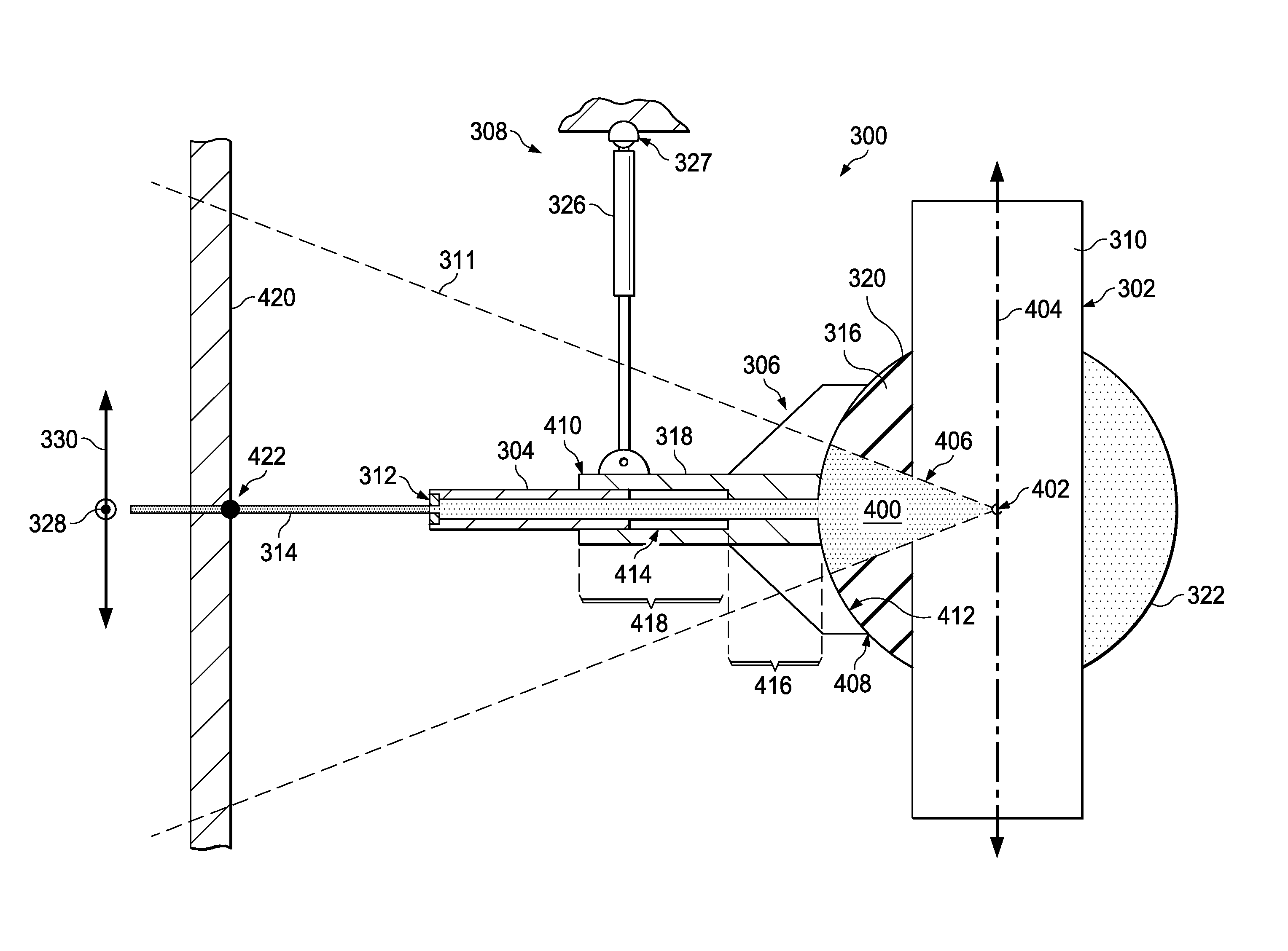
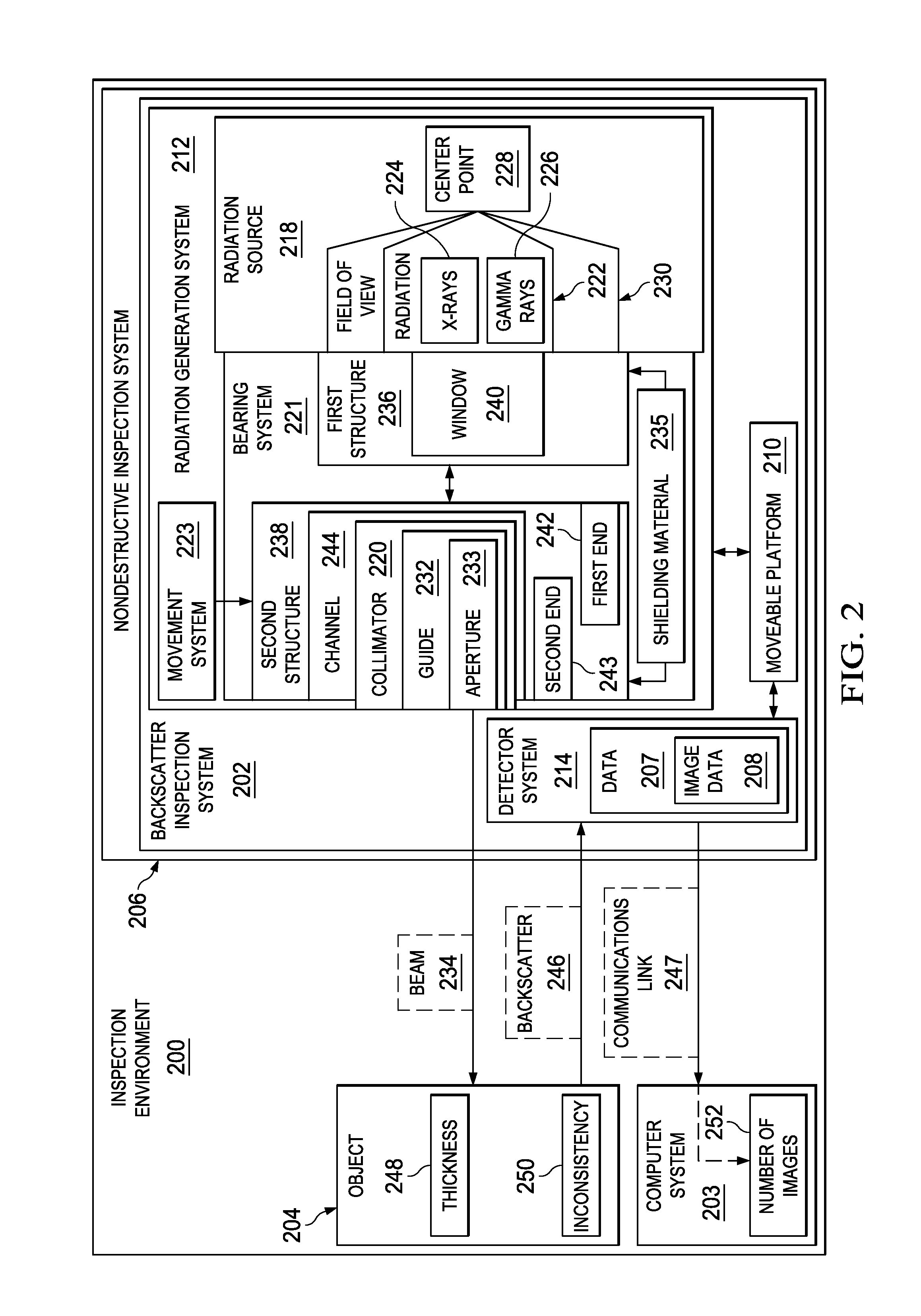
A method and apparatus for inspecting an object is present. Radiation is emitted from a radiation source. A beam is formed from a portion of the radiation emitted by the radiation source using a collimator. The collimator is connected to the radiation source by a bearing system comprising a first structure associated with the radiation source and a second structure connected to the first structure. The second structure is configured to hold the collimator. The second structure of the bearing system is moved using a movement system such that the second structure rotates in one of a plurality of directions substantially about a center point in the radiation source while the radiation source remains stationary relative to the second structure. Rotation of the second structure substantially about the center point in the radiation source changes a direction in which the beam is directed.

Description

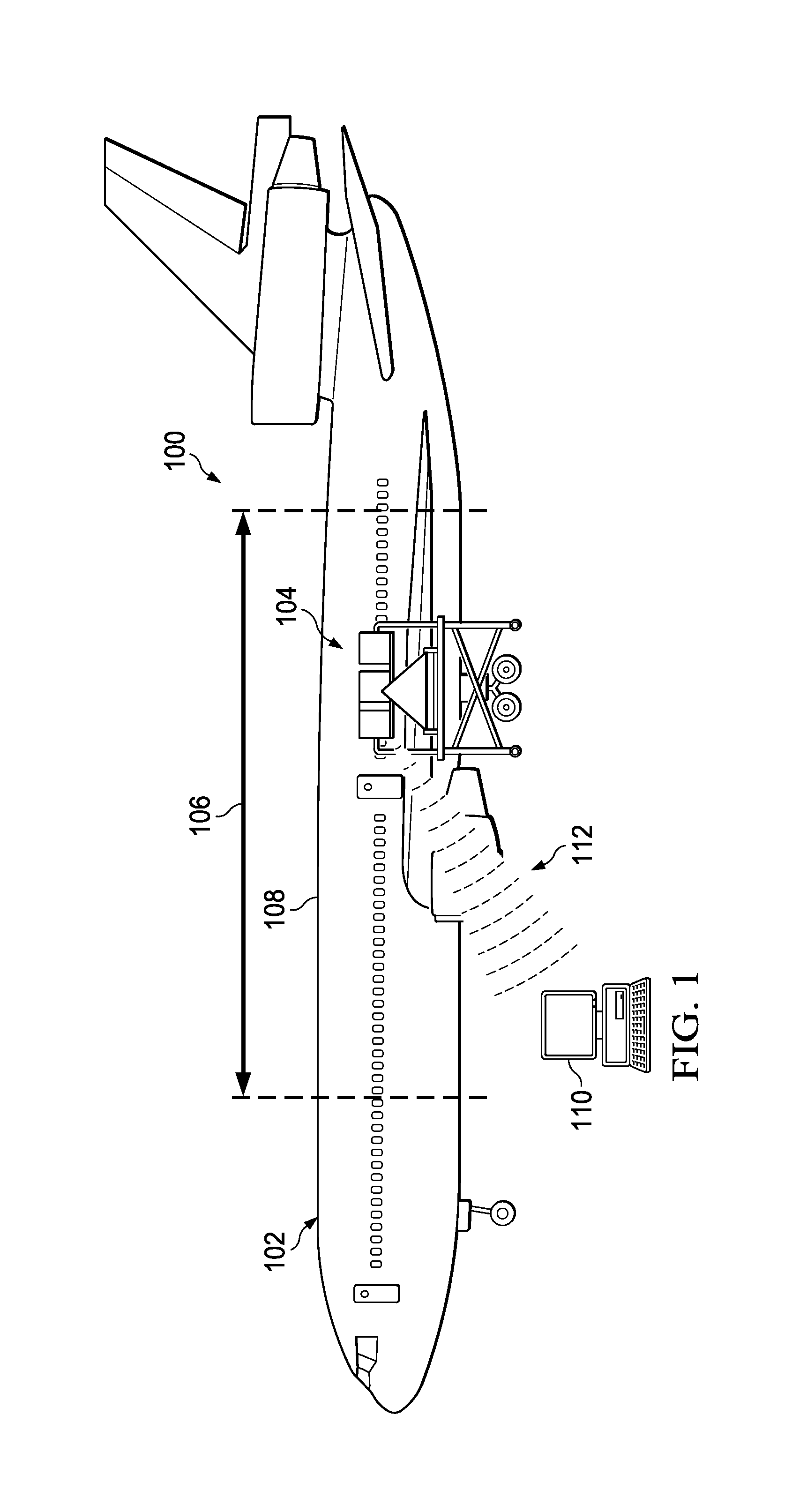
BACKGROUND INFORMATION[0001]1. Field[0002]The present disclosure relates generally to inspection systems and, in particular, to backscatter inspection systems. Still more particularly, the present disclosure relates to a method and apparatus for inspecting an object by moving a beam of radiation along the object in a selected pattern and detecting the backscatter formed in response to the beam encountering the object.[0003]2. Background[0004]Some currently available nondestructive inspection systems use radiation to inspect an object. The radiation may take the form of, for example, without limitation, x-rays, gamma rays, neutrons, or some other suitable type of radiation. A backscatter x-ray system is one example of a nondestructive inspection system that uses x-rays to inspect an object.[0005]Some currently available backscatter x-ray systems include an x-ray tube, a collimator, and a detector system. The x-ray tube generates and emits x-rays. The collimator filters these x-rays t...

Claims


Application Information

Patent Timeline
Patent Type & Authority Patents(United States)
IPC IPC(8): G01N23/203G21K1/04G01N23/00G21K5/04G01K1/02
CPCG21K1/04G01K1/02G01N23/005G01N2223/063G01N2223/3301G01N2223/646G21K5/04G01N23/203
Inventor LIESENFELT, MICHAELEDWARDS, WILLIAM TALIONSHEDLOCK, DANIEL
Owner THE BOEING CO
Learn More