Waterproof watch pushbutton

a pushbutton and watch technology, applied in the field of waterproof pushbutton for watch, can solve the problems of inconvenient use, unsuitable use, sealing, etc., and achieve the effect of ensuring reliability of engagement under water, effective activation, and reducing travel

Active Publication Date: 2015-09-01
THE SWATCH GRP RES & DEVELONMENT LTD
View PDF15 Cites 87 Cited by
  • Summary
  • Abstract
  • Description
  • Claims
  • Application Information

AI Technical Summary

Benefits of technology

[0009]An advantage of the proposed solution is to enable the seal to be guaranteed in relation to the interior of the watch case, in contrast to the usual solutions of completely mechanical pushbuttons, and also to minimise the travel required for the pushbutton head, which must be relatively long for usual wristwatches in order to compensate all tolerance errors of placement of different pieces and thus guarantee an effective activation by mechanical engagement each time the pushbutton head is pressed in.
[0010]Another advantage of the proposed solution is to guarantee reliability of engagement under water for a dive watch, for example, solely after the pushbutton has been pressed without being disturbed by automatic detection of the presence of the water when immersed in contrast to a classic capacitive solution that would no longer be able to detect the actual pressing of the pushbutton.
[0011]An additional advantage of the proposed solution is to provide, according to a preferred embodiment, a “click effect”, i.e. a mechanical feedback to the user of activation of the desired function on the basis of the elastic deformation of a capsule used to seal the device in relation to the exterior of the centrepart. As soon as the curvature of this capsule is inverted, the user will know that the function has been activated, irrespective of whether this has come into contact with an abutment surface or not, in particular for a capacitive mode of detection.

Problems solved by technology

However, this solution poses problems of sealing in relation to the interior of the case.
Moreover, compression of the joints greatly increases the force threshold to be applied to press in the pushbutton, which makes use relatively inconvenient.
This type of device can certainly allow physical isolation of the interior of a case in theory, since it does not require a transverse element similar to the usual solution for watch pushbuttons, but it still has the disadvantage of automatically detecting a variation in electrical capacitance on contact with water, which makes it unsuitable for use when immersed where it would no longer be possible to dissociate the actual activation by the user from that caused merely by contact with water.
Moreover, the adaptation of such a device to the dimensions of a wristwatch poses substantial problems in terms of detection thresholds, since the capacitance depends, amongst other factors, on a relation between the surface of the armatures and their spacing, which becomes difficult to manage when the contact surfaces are considerably reduced and, above all, when the minimum spacing between the armatures is relatively large, which is the case when the conductive elements of the capacitance used for the detection are arranged on either side of a hermetic insulating plate.
However, such devices are likewise unsuitable for use under water because of their lack of seal, nor can they be replicated for a wristwatch because of the high consumption of electric power necessary for permanent charging of the detection circuit, which would have a very negative impact on the service life of the battery.
However, the seal of the pushbutton is only assured by O ring-type seals in accordance with classic mechanical pushbuttons with the same disadvantages of reliability in terms of hermetic seal for activation when immersed and of the minimum force threshold to be applied because of the deformation of the joint.

Method used


Image

  • Waterproof watch pushbutton
  • Waterproof watch pushbutton
  • Waterproof watch pushbutton

Examples


Embodiment Construction

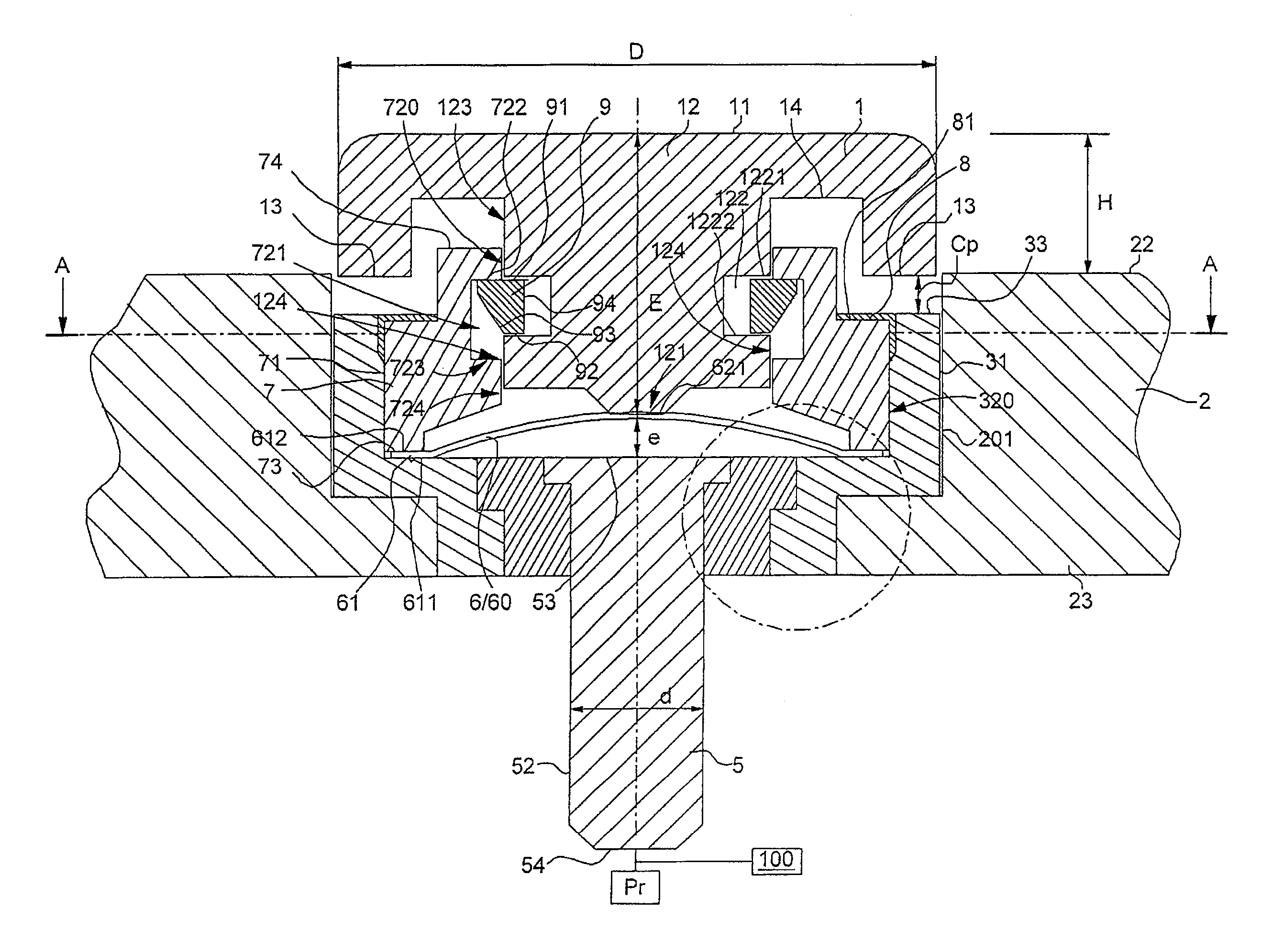
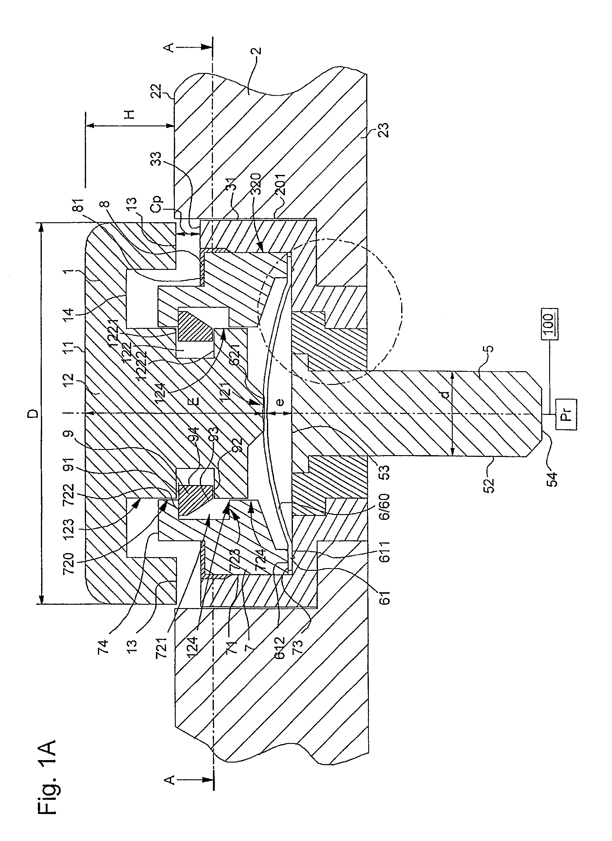
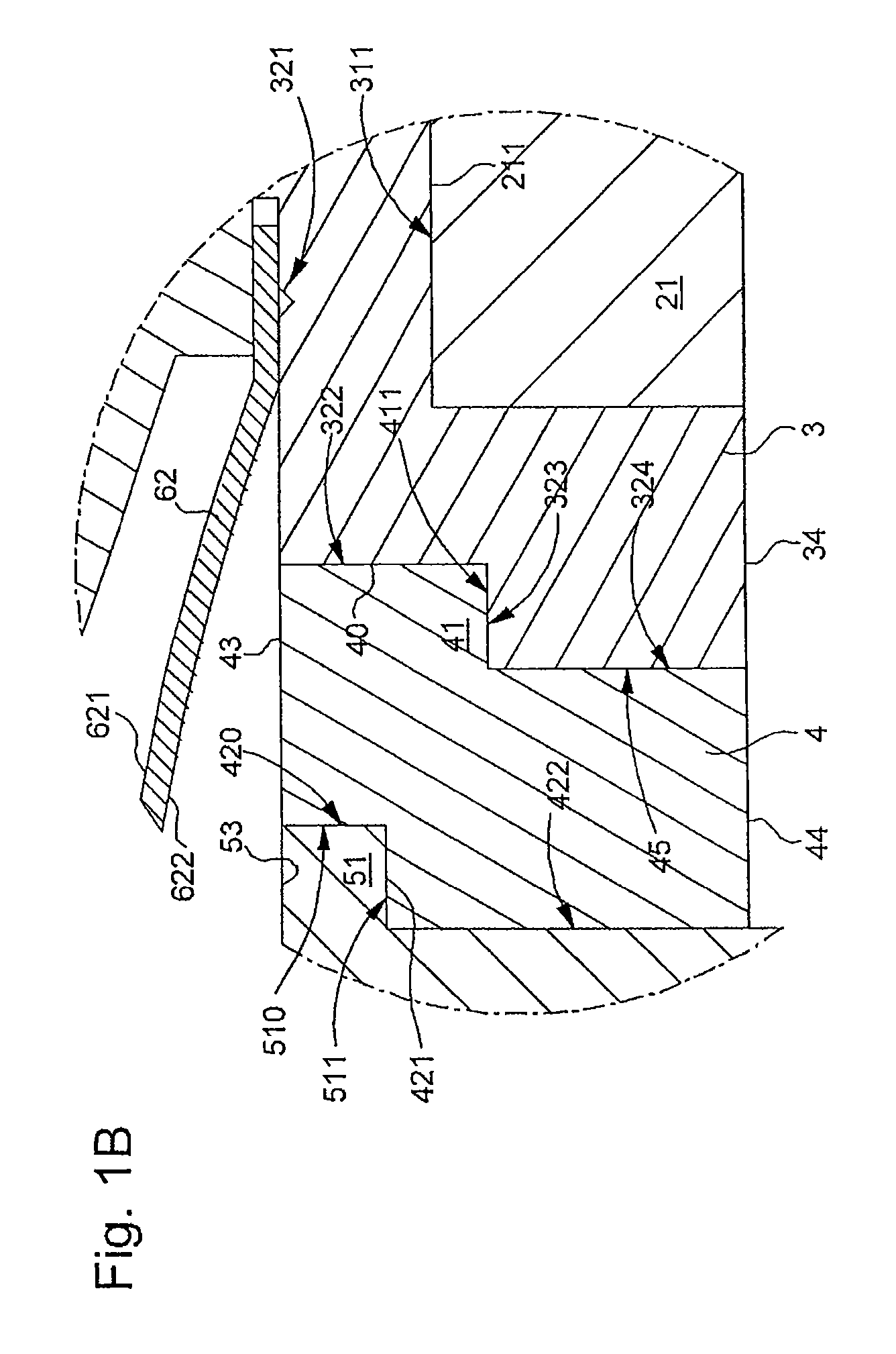
[0019]The following FIGS. 1A, 1B and 1C show two different views respectively in section and in plan view of a pushbutton according to a preferred embodiment of the invention, in which the pushbutton head 1 projects slightly out of the centrepart 2 of the watch when the pushbutton is in the resting position Pr. According to this preferred embodiment the pushbutton can be assembled in modular fashion outside the centrepart 2 before being inserted into a through hole 20 of the centrepart 2 illustrated in FIG. 1D. FIG. 1B is simply an enlargement of FIG. 1A in the area of the assembly of different parts. Since this FIG. 1B was introduced for reasons of legibility in order to add thereto references relating to the different pieces illustrated, these two figures will be referred to in combination in the following for specification of the references of the pieces described in the description.

[0020]As can be seen from the sectional view in FIG. 1A, the pushbutton head 1 comprises an upper ...


PUM


Abstract

A sealed pushbutton for a wristwatch includes a pushbutton head that is movable between a resting position and an active position, a first fixed conductive element, a second movable conductive element, and an elastically deformable capsule. The elastically deformable capsule hermetically covers the first fixed conductor, and an upper surface of the capsule is in physical contact with a lower surface of the pushbutton head and the capsule is locatable in a non-deformed position when the pushbutton head is in its resting position and in a deformed position when the pushbutton head is in its active position. The first and second conductive elements form a capacitive or resistive switch device, and the switch is in open state when the pushbutton head is in its resting position and in closed state when the pushbutton head is in its active position.

Description

[0001]This application claims priority from European Patent Application No. 11195404.6 filed Dec. 22, 2011, the entire disclosure of which is incorporated herein by reference.FIELD OF INVENTION[0002]The present invention relates to a waterproof pushbutton for a wristwatch and more specifically to a sealed pushbutton for an electronic watch comprising a capacitive or resistive switch device.BACKGROUND OF THE INVENTION[0003]Classic mechanical pushbuttons generally comprise a transverse head in relation to the centrepart of a watch case, of which a lower end comes to rest against a movable or plastically deformable element such as a blade of an operating device, for example. When the pushbutton is pressed in, the end of this transverse head causes the movable element to move, and this comes into abutment to activate a mechanical or electronic function. Moreover, the coming into abutment enables the user to have a mechanical confirmation of the actual activation of the desired function ...

Claims


Application Information

Patent Timeline
Patent Type & Authority Patents(United States)
IPC IPC(8): G04B37/00H01H13/06G04B29/00G04C3/00G04G17/00G04B3/04G04B37/10H03K17/975H03K17/96
CPCH01H13/06G04B3/046G04B3/048G04B37/106G04C3/001G04G17/00H03K17/962H03K17/975
Inventor FERRI, YVANROTA, SERGIOMARTIN, JEAN-CLAUDE
Owner THE SWATCH GRP RES & DEVELONMENT LTD
Why Eureka
Try Eureka