Air bag system having diffuser structure

a technology of air bags and diffusers, which is applied in the direction of superstructure subunits, pedestrian/occupant safety arrangements, vehicle components, etc., can solve the problems of reducing handling ease, difficult to complete the deployment of the air bag within a sufficiently short time, and reducing the distance from the gas inlet of the air bag to the inflatable portions of the air bag, so as to reduce the flow resistance of the diffuser, the time required for completing the deployment of the air bag can be advantageously shortened

Inactive Publication Date: 2008-05-13
TOYOTA JIDOSHA KK
View PDF21 Cites 5 Cited by
  • Summary
  • Abstract
  • Description
  • Claims
  • Application Information

AI Technical Summary

Benefits of technology

[0008]With the air bag system constructed as described above, the gas inlet is provided in a longitudinally middle portion of the air bag, and the distance over which the gas travels from the inflator to the gas inlet of the air bag can be minimized. In addition, the distance from the gas inlet of the air bag to inflatable portions of the air bag can be advantageously reduced. With this arrangement, the flow resistance of the diffuser can be reduced, and gas can be guided to the inflatable portions as end portions of the air bag within a short time. Thus, the time required for completing deployment of the air bag can be advantageously shortened.

Problems solved by technology

With this arrangement, while gas may be guided from the inflator into the air bag with high accuracy, it is difficult to guide the gas from the inflator to inflatable chambers formed in middle and front end portions of the air bag within a sufficiently short period of time, because of relatively long distances from the inflator to the middle portion and front end portion of the air bag.
It is thus difficult to complete deployment of the air bag within a sufficiently short time.
Furthermore, the known diffuser having a large length may cause various problems, such as reduced handling ease at the time of, for example, loading into a plant or installation of the air bag system in the vehicle, increased cost and weight, and increased loss of space upon installation of the system on the vehicle.
The cost of the diffuser may also be increased because multiple gas outlet ports are formed in the long diffuser in different cutting processes.

Method used


Image

  • Air bag system having diffuser structure
  • Air bag system having diffuser structure
  • Air bag system having diffuser structure

Examples


Embodiment Construction

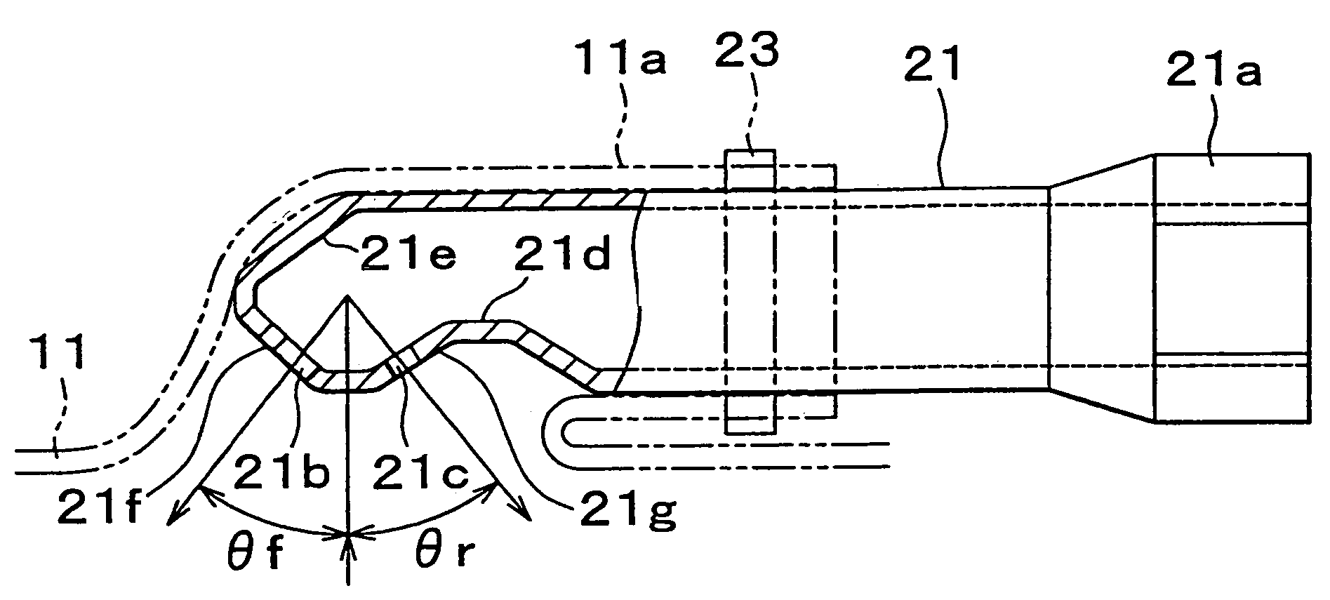
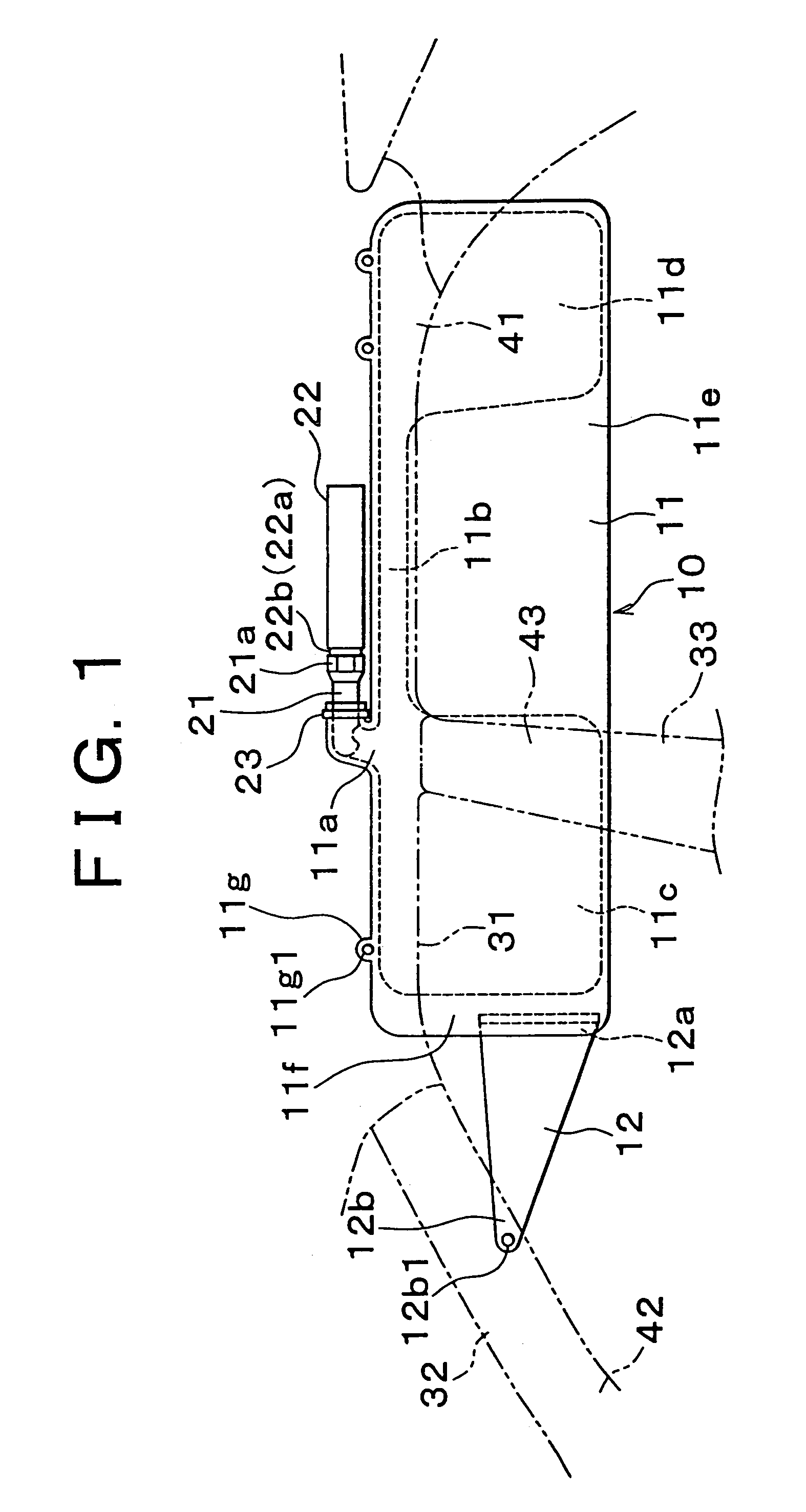
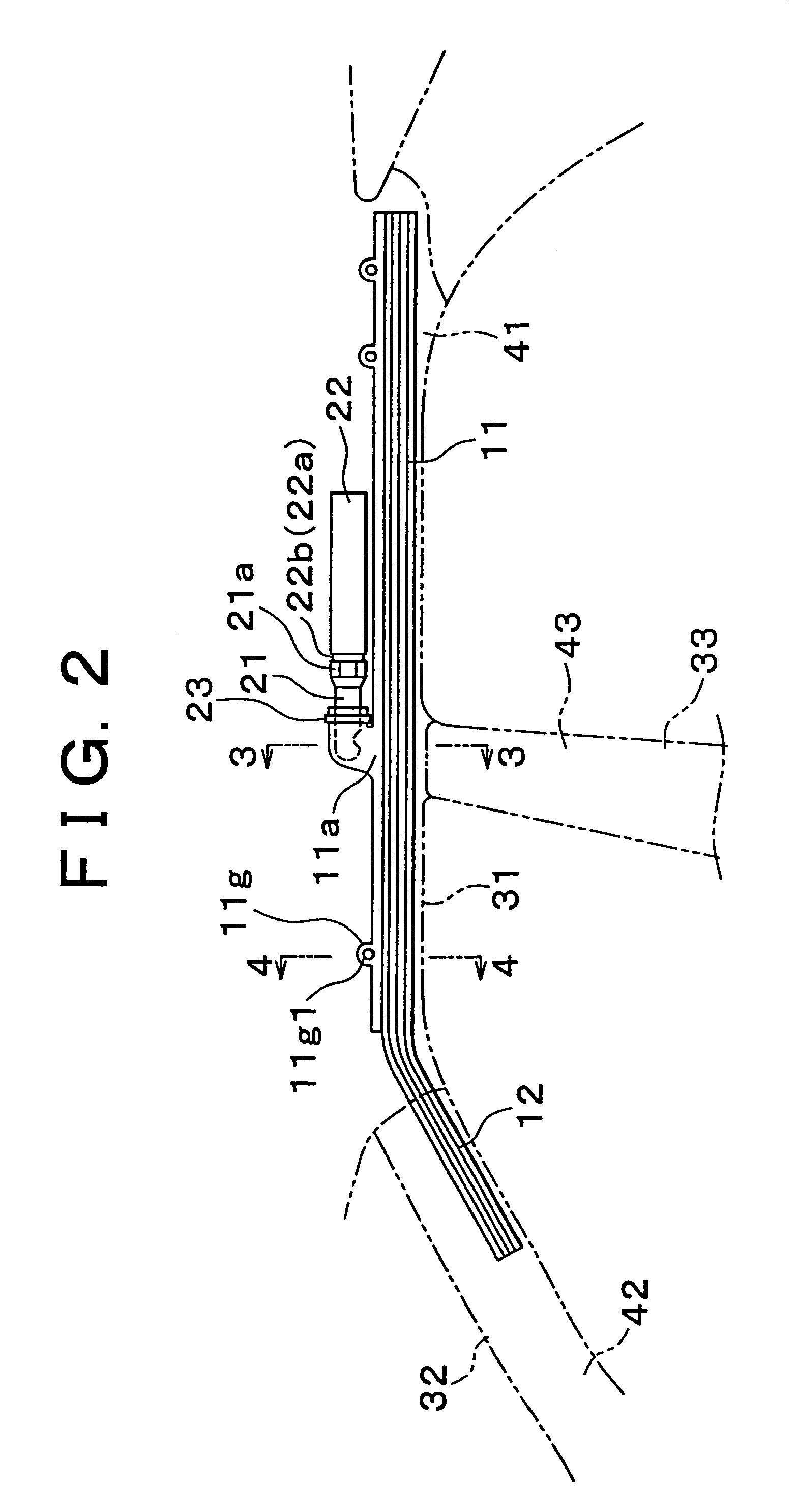
[0030]Hereinafter, one exemplary embodiment of the invention will be described with reference to the accompanying figures. FIGS. 1 to 6 show a head-protection air bag system designed for passenger vehicles according to one embodiment of the invention. The head-protection air bag system of the embodiment includes an air bag 10 and an inflator 22. The air bag 10 is inflated into the shape of a curtain at a side region of a passenger compartment of the vehicle, thus protecting front-seat and rear-seat occupants (not shown) from head injury. The inflator 22 supplies the air bag 10 with gas via a diffuser 21. The air bag 10 includes an air bag body 11 and a tension cloth 12. The air bag body 11 has inflatable portions and non-inflatable portions. The tension cloth12, which has no inflatable portion, is attached to a front-end portion of the air bag body 11.

[0031]The air bag body 11 is woven into the shape of a bag in such a manner that weave patterns extend in both longitudinal and verti...


PUM


Abstract

An air bag system is provided in which an air bag stored in a folded state in a vehicle is adapted to be inflated by a gas supplied from an inflator through a diffuser so as to protect an occupant of the vehicle. In the air bag system, the diffuser is disposed on one side of the inflator such that the diffuser and the inflator are substantially aligned with each other, and the diffuser includes a gas feed portion that is exposed to a gas inlet formed in a generally middle portion of the air bag as viewed in a longitudinal direction thereof.

Description

BACKGROUND OF THE INVENTION[0001]1. Field of Invention[0002]The invention generally relates to an air bag system installed in a motor vehicle and a diffuser used in the air bag system, and more particularly to an air bag system in which an air bag, which is stored in a folded state in a certain portion of the vehicle, is adapted to deploy by using gas supplied from an inflator via a diffuser, in order to protect a vehicle occupant or occupants.[0003]2. Description of Related Art[0004]In a known air bag system of the above type as disclosed in, for example, Japanese Laid-Open Patent Publication No. 11-301394, a diffuser (connecting line) having a great length is disposed in front of an inflator so as to extend in a curved form in the longitudinal direction of the vehicle. The diffuser is inserted in the air bag through a gas inlet port formed in a longitudinally end portion (i.e., rear end portion) of the air bag. The inflator supplies a gas into the air bag via gas supply ports (a l...

Claims


Application Information

Patent Timeline
Patent Type & Authority Patents(United States)
IPC IPC(8): B60R21/16B60R21/20B60R21/213B60R21/21B60R21/232B60R21/26B60R21/262B62D25/06
CPCB60R21/26B60R21/261B60R21/213B60R21/232B62D25/06B60R21/21
Inventor TOKUNAGA, SHINYAOHNO, MITSUYOSHI
Owner TOYOTA JIDOSHA KK
Why Eureka
Try Eureka