Guide device for a centrifugal blower

a centrifugal blower and guide device technology, applied in the direction of machines/engines, stators, liquid fuel engines, etc., can solve the problems of turbulence and noise, accumulation of pressure and fluid in the compartment, etc., and achieve the effect of reducing turbulence and nois

Active Publication Date: 2015-09-08
HANON SYST
View PDF23 Cites 4 Cited by
  • Summary
  • Abstract
  • Description
  • Claims
  • Application Information

AI Technical Summary

Benefits of technology

[0005]In concordance and agreement with the present invention, a centrifugal blower including a shield that performs as a tunable guide device to minimize turbulence, noise, and a recirculation flow of the fluid at the fluid inlet of the housing, has surprisingly been discovered.

Problems solved by technology

The shield is typically stationary and a proximity of an edge of the shield to the rotating blades of the impeller can cause turbulence and noise.
In some instances, the flow resistance during the floor, the heating, and the defrost modes can cause an accumulation of pressure and fluid in the compartment.

Method used


Image

  • Guide device for a centrifugal blower
  • Guide device for a centrifugal blower
  • Guide device for a centrifugal blower

Examples


Embodiment Construction

[0014]The following detailed description and appended drawings describe and illustrate various exemplary embodiments of the invention. The description and drawings serve to enable one skilled in the art to make and use the invention, and are not intended to limit the scope of the invention in any manner.

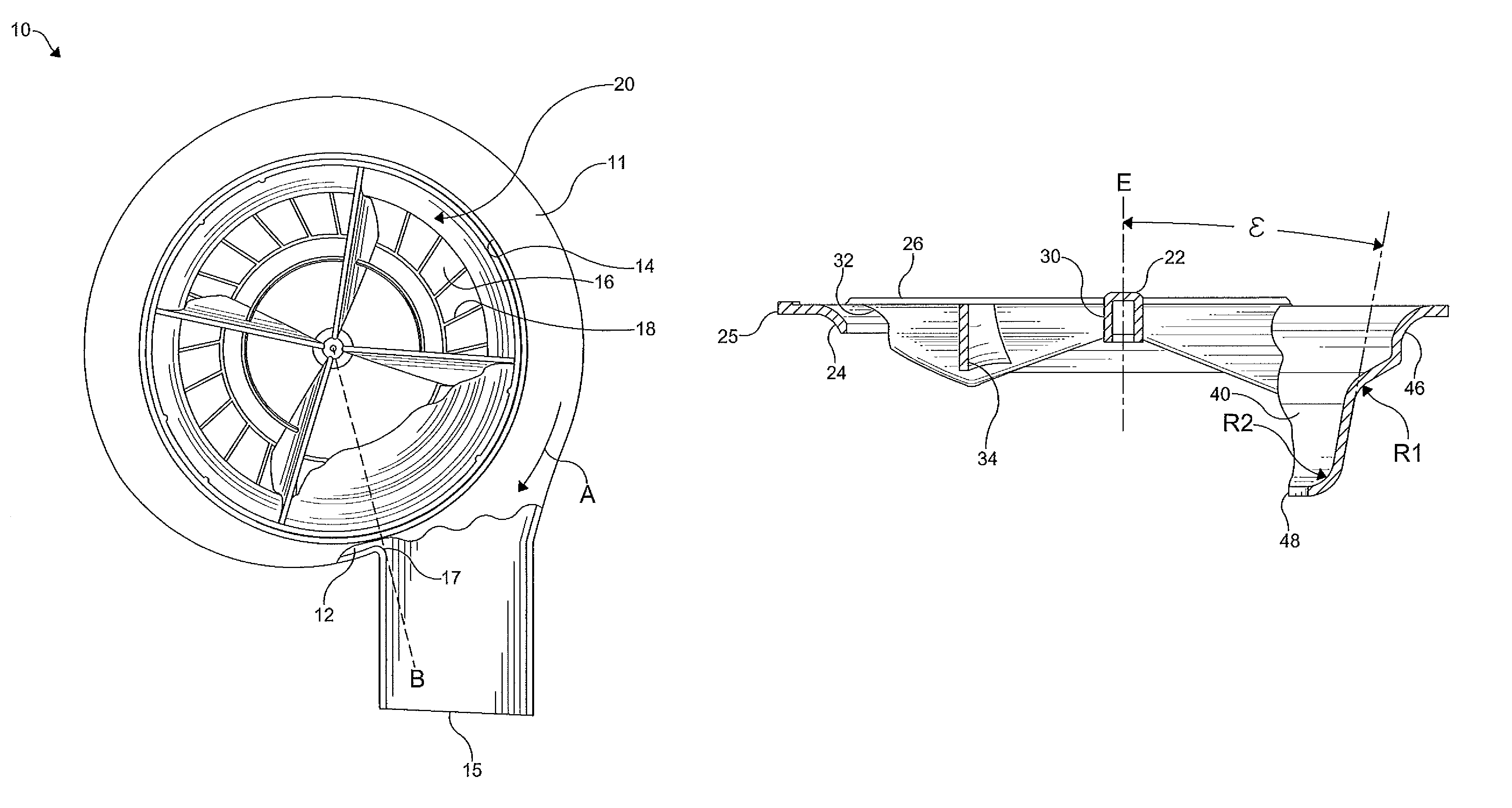
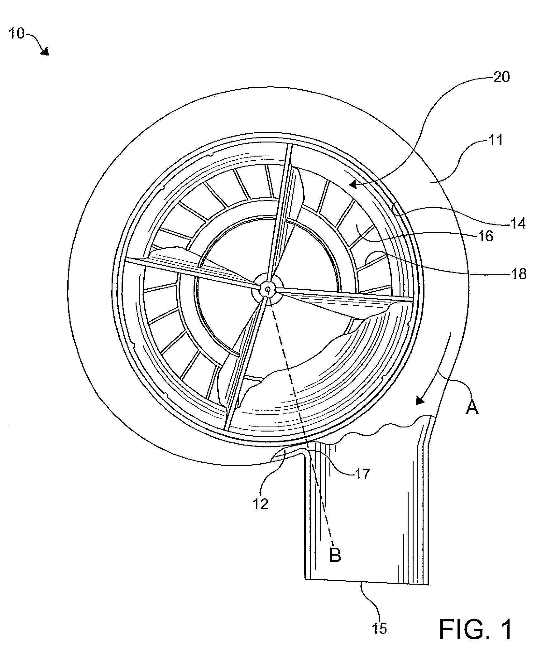
[0015]FIG. 1 shows a centrifugal blower 10 in accordance with the present invention. The blower 10 includes a housing 11 having a compartment 12, an axial fluid inlet 14, and a tangential fluid outlet 15. In the embodiment shown, the fluid inlet 14 is a central opening formed in the housing 11. An impeller 16 having a plurality of blades 18 arranged around a rotational axis of the impeller 16 is disposed in the compartment 12 of the housing 11. The blades 18 are annularly spaced from one another and attached to a hub (not shown) of the impeller 16 for rotation therewith. The impeller 16 shown is driven by a motor (not shown). It is understood, however, that the impeller 16 can be cau...


PUM


Abstract

A centrifugal blower including a hollow housing and an impeller having a plurality of blades disposed in the hollow housing, wherein the impeller causes a fluid received in a fluid inlet of the hollow housing to flow in a radially outward direction to a fluid outlet of the hollow housing. A guide device for directing the flow of the fluid in the blower is disposed in the fluid inlet of the hollow housing, the guide device including a shroud configured to militate against turbulence, noise, a recirculation of flow of the fluid at the fluid inlet, and interference between the guide device and balance weights of the blower during an assembly of the blower.

Description

FIELD OF THE INVENTION[0001]The present invention relates to a centrifugal blower and more particularly to a centrifugal blower including a guide device for directing a flow of a fluid therein.BACKGROUND OF THE INVENTION[0002]Centrifugal blowers known in the art typically include a housing having a compartment, an axial fluid inlet, and a radial fluid outlet. An impeller having a plurality of blades is disposed in the compartment of the housing. The blades are arranged around a rotational axis of the impeller and attached to a hub of the impeller for rotation therewith. Rotational movement of the impeller causes a flow of fluid received in the fluid inlet to flow in a radially outward direction in respect to the impeller to the fluid outlet. A shield may be provided in the fluid inlet to militate against inadvertent contact with the impeller and direct the flow of the fluid through the fluid inlet. The shield is typically stationary and a proximity of an edge of the shield to the ro...

Claims


Application Information

Patent Timeline
Patent Type & Authority Patents(United States)
IPC IPC(8): F04D29/44
CPCF04D29/441
Inventor GOENKA, LAKHI NANDLAL
Owner HANON SYST
Why Eureka
Try Eureka