Test station for portable gas measuring devices

a gas measuring device and portable technology, applied in the direction of measuring devices, material analysis through optical means, instruments, etc., to achieve the effect of reducing the consumption of test gas and accelerating the process

Active Publication Date: 2015-09-08
DRAGER SAFETY
View PDF4 Cites 10 Cited by
  • Summary
  • Abstract
  • Description
  • Claims
  • Application Information

AI Technical Summary

Benefits of technology

[0009]An object of the present invention is to improve a test station for portable gas measuring devices of the type mentioned in the introduction, such that tests on a plurality of gas measuring devices, which have been inserted into test modules one after the other and whose tests have started one after the other, can be carried out more rapidly. Further, the consumption of test gas shall be reduced in such cases.
[0011]Because of the parallel processing of a plurality of test modules at the same time, a plurality of gas measuring devices can be tested more rapidly, since their processing can take place in parallel and not in succession as in the state of the art. Further, the consumption of test gases is reduced, since each test gas fed through the common gas line for a plurality of test modules can be used at the same time. In addition, the carrier of the gas measuring device can initiate the test independently of the main unit in a decentralized manner directly at the test module used by him; the test then begins as soon as a test gas suitable for the gas measuring device is present and the control and analysis unit releases the feed from the gas line to the test module.
[0015]In this way, the carrier of the gas measuring device can pick up this gas measuring device and insert it into a free test module and then initiate the display of the readiness for testing to the control and analysis unit locally at the test module in order to thus release the test for the inserted gas measuring device in a decentralized manner.

Problems solved by technology

In everyday operation, however, the situation frequently arises that a plurality of operators insert their gas measuring device into a test module chronologically one after the other and then want to have a test result as soon as possible.

Method used


Image

  • Test station for portable gas measuring devices
  • Test station for portable gas measuring devices
  • Test station for portable gas measuring devices

Examples


Embodiment Construction

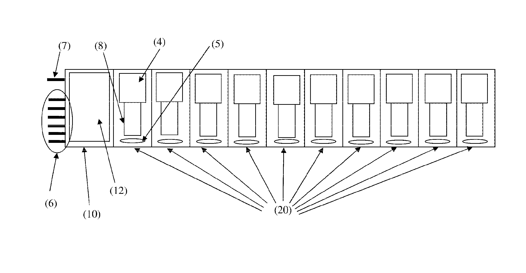
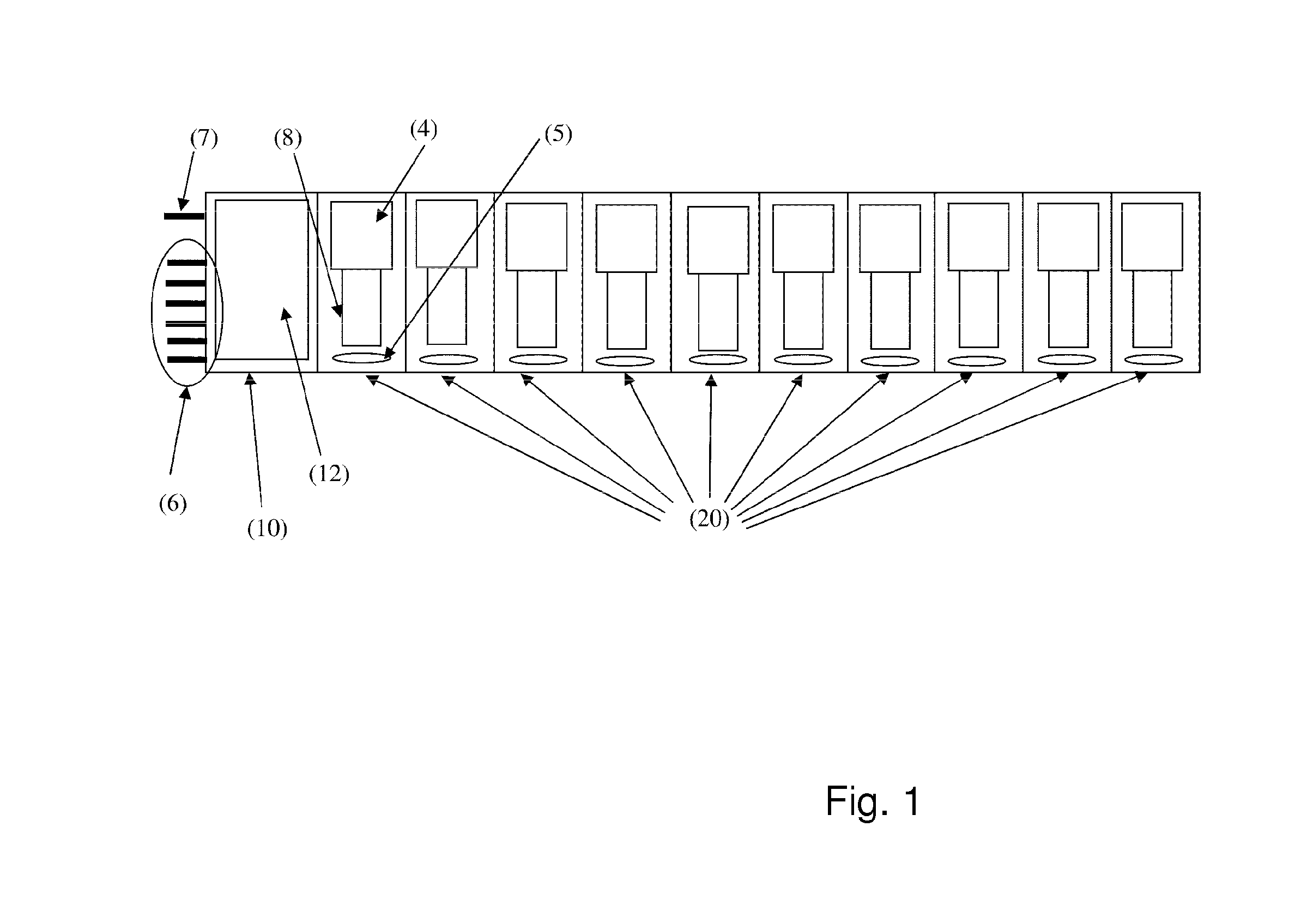
[0023]Referring to the drawings in particular, the test station schematically shown in FIG. 1 comprises a main unit 10 and ten test modules 20 in this exemplary embodiment. The main unit 10 is connected to the test modules 20 by means of a bidirectional data link for the purpose of exchanging data. Further, a common gas line leads out of the main unit 10 to the test modules; the test modules 20 are connected in parallel to the gas line and are each provided with valve means, which, controlled by the main unit 10, open or close the flow of test gas from the gas line to the individual test module.

[0024]In the exemplary embodiment shown, six gas inlets 6 for different test gases are provided at the main unit 10. After selecting one of the gas inlets 6, the common gas line is supplied with the selected test gas. The test gas is again discharged to the outside by means of the waste gas line 7.

[0025]When a gas measuring device 8 is inserted into one of the test modules 20 and the flap 4 i...


PUM

PropertyMeasurementUnit
timeaaaaaaaaaa
concentrationsaaaaaaaaaa
concentrationaaaaaaaaaa

Abstract

A test station for a plurality of test gases, includes a main unit (10) with a control (12) and test modules (20), each for a gas measurement device, that exchange data to register a type of gas measurement device and test gas(es) required for the device type. The control sets a schedule for a test using a test gas, or for a plurality of successive tests each with different test gases and carries out the specific test planned according to the schedule, in parallel with tests for all of the test modules for a test gas and determines, as an additional gas measurement device is inserted, based on the particular device type of the additional gas measurement device, whether the currently-running test with the current test gas is suitable for the inserted test module; and if the test gas is suitable, to start the test for this test module.

Description

CROSS REFERENCE TO RELATED APPLICATIONS[0001]This application is a United States National Phase Application of International Application PCT / EP2013 / 061916 filed Jun. 10, 2013 and claims the benefit of priority under 35 U.S.C. §119 of German Patent Application DE 10 2012 210 090.3 filed Jun. 15, 2012, the entire contents of which are incorporated herein by reference.FIELD OF THE INVENTION[0002]The present invention pertains to a test station for portable gas measuring devices for a plurality of test gases, comprising a main unit including a control and analysis unit, and comprising a plurality of test modules connected to the main unit for the purpose of exchanging data, into each of which a gas measuring device can be inserted for testing, whereby means are provided for detecting the type of the respective gas measuring device that has been inserted into a test module and for determining the test gas or test gases required for this type of device, and whereby the main unit comprises...

Claims


Application Information

Patent Timeline
Patent Type & Authority Patents(United States)
IPC IPC(8): G01N21/00G01N33/00
CPCG01N33/0006G01N33/0004G01N33/007
Inventor OSTERMANN, ULFKANEBLEI, INGOBARTEN, STEFANMOLLER, CHRISTOFSCHIMMEL, SVEN
Owner DRAGER SAFETY
Why Eureka
Try Eureka