
System and method for reconstructing cardiac activation information

a cardiac activation and information technology, applied in the field can solve the problems of significant morbidity and death in the world, inappropriate sinus tachycardia or sinus node reentry, and difficult treatment of heart rhythm disorders, especially complex rhythm disorders of af, vf and polymorphic v

Active Publication Date: 2013-08-29
TOPERA +2
View PDF2 Cites 36 Cited by
  • Summary
  • Abstract
  • Description
  • Claims
  • Application Information

AI Technical Summary

Benefits of technology

The present invention is about a system and method to reconstruct cardiac activation information and determine the cause and source of complex heart rhythm disorders. This information can be used to treat the disorder by quickly carrying out the necessary treatment. The invention is advantageous in that it can help diagnose and cure heart rhythm disorders in a rapid and accurate way, which can ultimately save time and lives.

Problems solved by technology

Heart (cardiac) rhythm disorders are common and represent significant causes of morbidity and death throughout the world.
While under normal conditions the sinus node keeps the heart in sinus rhythm, under certain conditions rapid activation of the normal sinus node can cause inappropriate sinus tachycardia or sinus node reentry, both of which also represent heart rhythm disorders.
Treatment of heart rhythm disorders—particularly complex rhythm disorders of AF, VF and polymorphic VT—can be very difficult.
Pharmacologic therapy for complex rhythm disorder is not optimal, with poor efficacy and significant side effects.
However, in complex rhythm disorders ablation is often difficult and ineffectual because tools that identify and locate a cause of the heart rhythm disorder are poor and hinder attempts to deliver energy to the correct region of the heart to eliminate the disorder.
Even in simple heart rhythm disorders, such ablation of the cause of a heart rhythm disorder is challenging and experienced practitioners often require hours to ablate simple rhythm disorders with consistent beat-to-beat activation patterns, such as atrial tachycardia.
There are no known systems and methods that have been successful with respect to identifying causes for the complex rhythm disorders such as AF, VF or polymorphic VT.
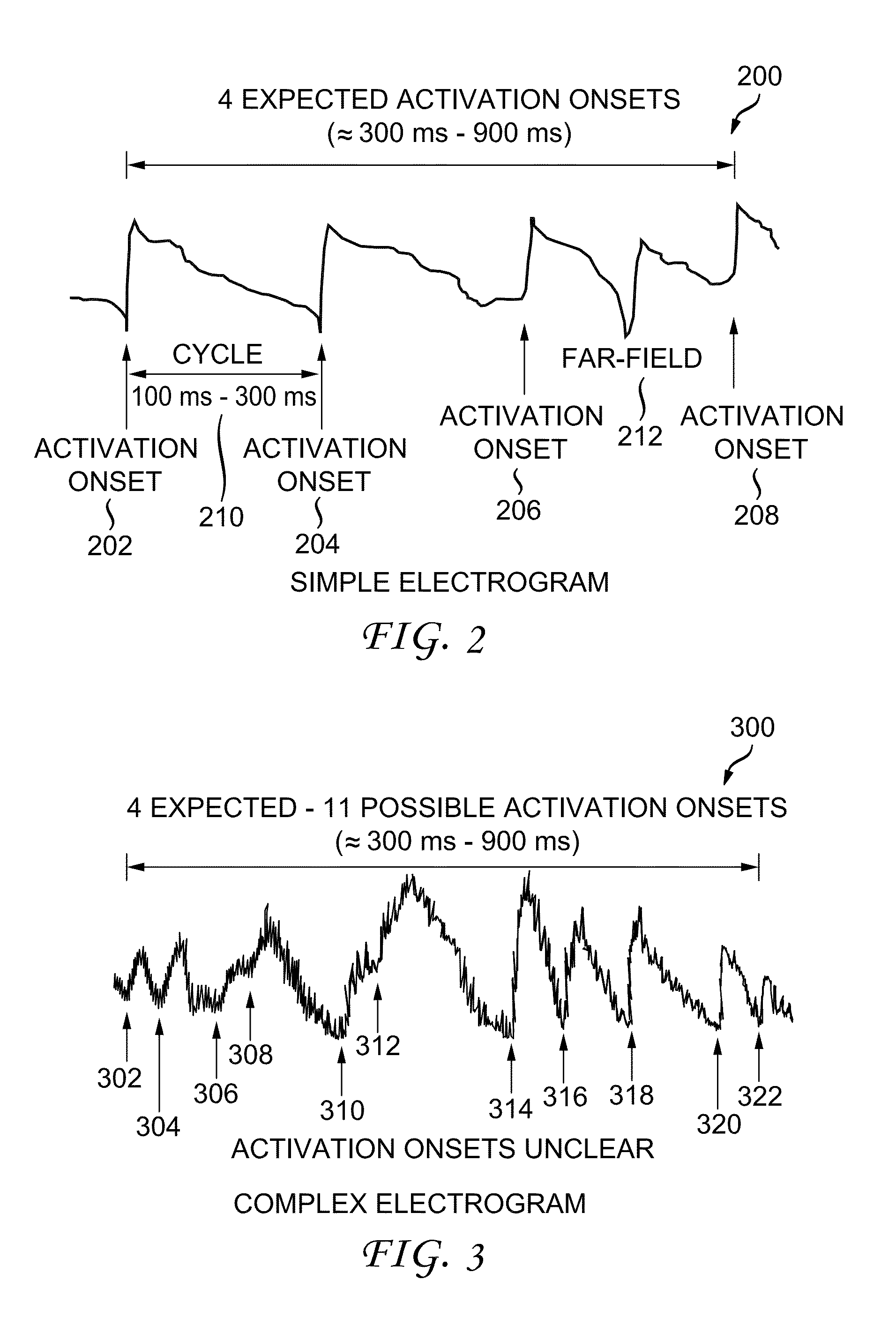
For instance, when a signal for a sensor location in AF includes 5, 7, 11 or more deflections, it is difficult if not impossible to identify which deflections in the signal are at or near the sensor location in the heart (i.e., local activation) versus a further removed location still sensed by the sensor in the heart (i.e., far-field activation) or simply noise from another part of the patient's heart, other anatomic structures, movement or motion of the sensor relative to the heart or external electronic systems.
There are no known systems and methods that have been able to reconstruct cardiac activation information (onsets) in variously shaped signals associated with heart rhythm disorders, especially in complex rhythm disorders, to facilitate identification of a cause of the heart rhythm disorders and their elimination.
Complex heart rhythm disorders typically result in activation patterns that are extremely difficult to decipher and the ability to determine accurate activation information of heart beats in complex disorders has previously not been possible.
Prior systems and methods suffered from the inability to determine the source of heart rhythm disorders and consequently provided no means of targeting the source for meaningful and curative treatment.
Additionally, prior systems and methods required numerous and complex steps of treatment and yet still failed to provide a means of reconstructing cardiac activation information sufficient to identify the cause(s) or source(s) of the heart rhythm disorder.

Method used


Image

  • System and method for reconstructing cardiac activation information
  • System and method for reconstructing cardiac activation information
  • System and method for reconstructing cardiac activation information

Examples


Embodiment Construction

[0037]A system and method for reconstructing cardiac activation information associated with heart rhythm disorders are disclosed herein. In the following description, for the purposes of explanation, numerous specific details are set forth in order to provide a thorough understanding of example embodiments or aspects. It will be evident, however, to one skilled in the art, that an example embodiment may be practiced without all of the disclosed specific details.

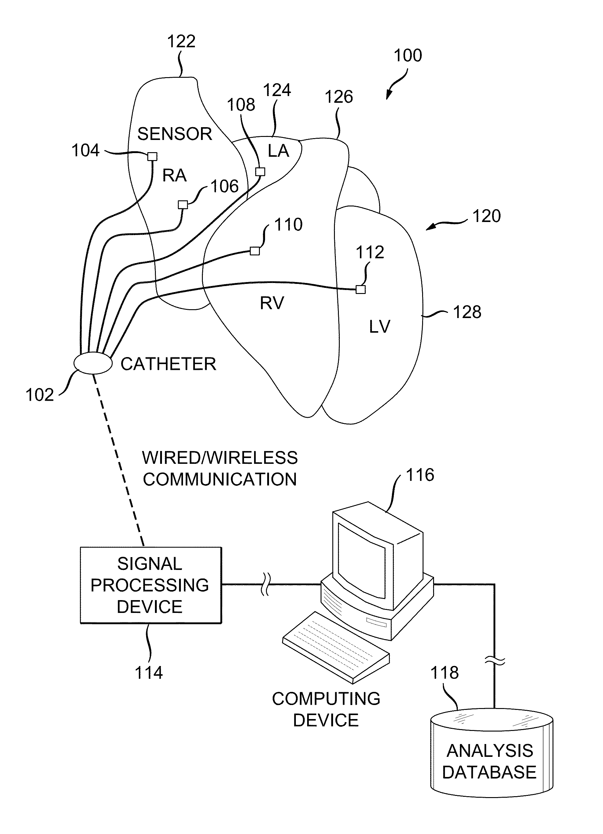
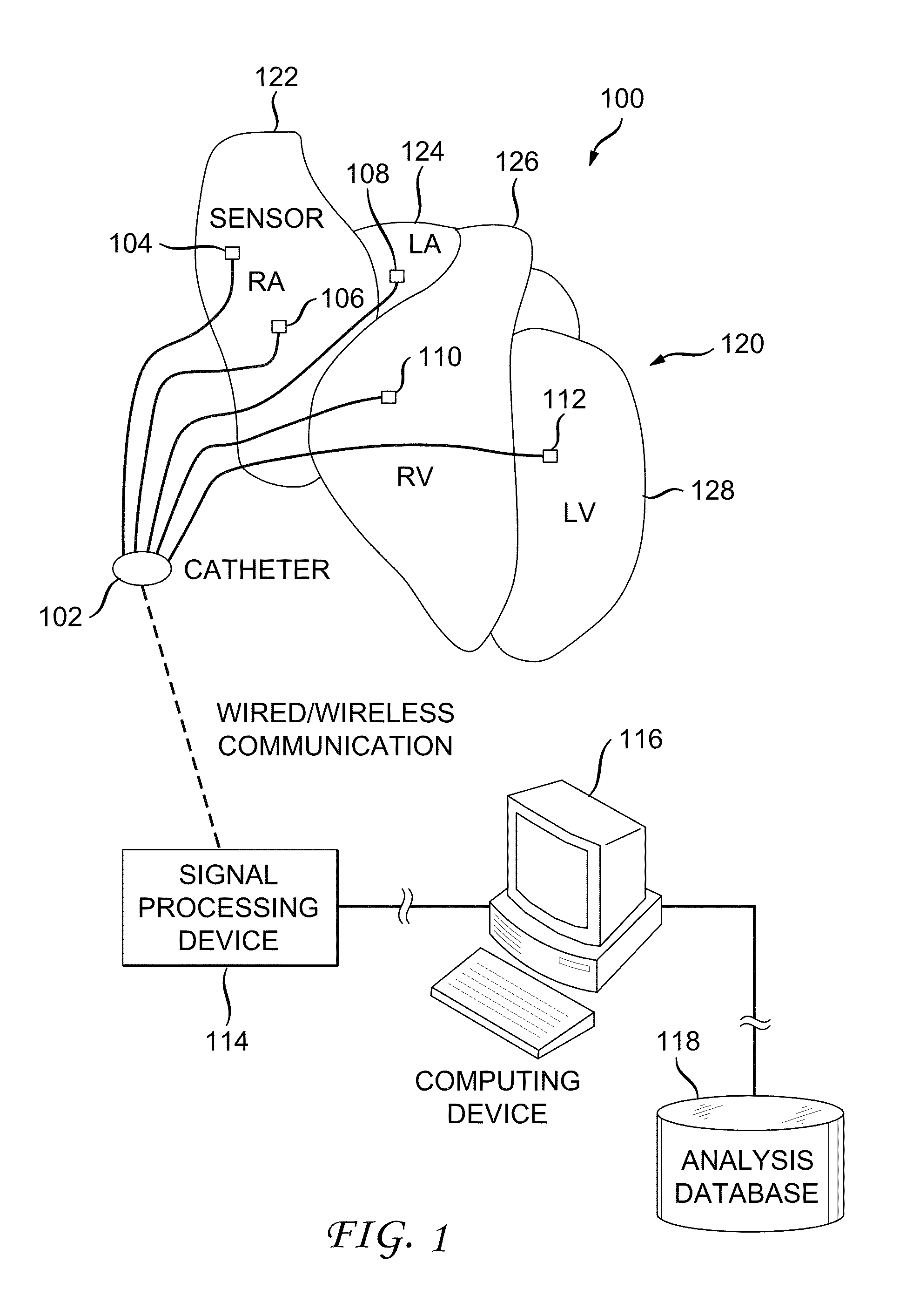
[0038]FIG. 1 illustrates an example cardiac activation reconstruction system 100. The example system 100 is configured to detect and reconstruct cardiac activation information collected / detected from a patient's heart in connection with a heart rhythm disorder. The heart includes a right atrium 122, left atrium 124, right ventricle 126 and left ventricle 128.

[0039]The example system 100 includes a catheter 102, signal processing device 114, computing device 116 and analysis database 118.

[0040]The catheter 102 is configured to...


PUM


Abstract

An example system and method of reconstructing cardiac activation information are disclosed. An analysis signal and a reference signal are processed to determine whether there is a first point of change in a first selected-order derivative of the analysis signal with respect to a first selected-order derivative of the reference signal above a first threshold. The analysis signal and the reference signal are processed to determine whether there is a second point of change in a second selected-order derivative of the analysis cardiac signal with respect to a second selected-order derivative of the reference cardiac signal above a second threshold. An activation onset time is assigned in the analysis cardiac signal at a point based on a mathematical association of the first point of change and the second point of change to define cardiac activation indicating a beat in the analysis cardiac signal.

Description

CROSS REFERENCE TO RELATED APPLICATION[0001]This is a continuation-in-part of U.S. patent application Ser. No. 13 / 438,534 filed on Apr. 3, 2012, which is continuation of U.S. patent application Ser. No. 13 / 217,123 filed on Aug. 24, 2011, which claims priority to and benefit of U.S. Provisional Patent Application No. 61 / 481,607 filed on May 2, 2011, each of the applications incorporated herein by reference in its entirety.FEDERAL GRANT[0002]Some of the research described in this application was funded by Grants R01 HL83359, HL83359-S1 and HL103800 from the National Institutes of Health. The U.S. Government may therefore have certain rights in the invention.BACKGROUND[0003]1. Field[0004]The present application relates generally to heart rhythm disorders. More specifically, the present application is directed to a system and method for reconstructing cardiac activation information (activation onset) associated with heart rhythm disorders.[0005]2. Brief Discussion of Related Art[0006]He...

Claims


Application Information

Patent Timeline
Patent Type & Authority Applications(United States)
IPC IPC(8): A61B5/0452A61B5/361A61B5/363A61B5/364A61B5/366
CPCA61B5/0422A61B5/0452A61B5/7239A61B2562/046A61B5/7203A61B5/04011A61B5/04012A61B5/046A61B5/0464A61B5/0205A61B5/7282A61B5/7246A61B5/7278A61B5/0036A61B5/316A61B5/287A61B5/349A61B5/318A61B5/341A61B5/361A61B5/363A61B5/364A61B5/366A61B5/02405A61B5/0255A61B5/7217A61B5/742A61B5/7207A61B5/024A61B5/0245A61B5/6852
Inventor NARAYAN, SANJIVBRIGGS, CAREY ROBERTSEHRA, RUCHIR
Owner TOPERA
Learn More