
Vehicle lamp color-changing device with swingable arm

a technology of vehicle lamps and swinging arms, which is applied in the direction of fixed installation, transportation and packaging, lighting and heating equipment, etc., can solve the problems of affecting the design of the above-mentioned device, slow response, and further difficulties in spacial arrangement, and achieve the effect of convenient arrangemen

Inactive Publication Date: 2015-09-15
CHIANG NAN HSIN
View PDF4 Cites 0 Cited by
  • Summary
  • Abstract
  • Description
  • Claims
  • Application Information

AI Technical Summary

Benefits of technology

The device allows for fast and accurate color switching between two specific colors, preventing lens damage and noise, while being compact enough for easy integration into vehicle lamps, with a smaller rotary drive that maintains efficient operation.

Problems solved by technology

However, for the purpose of spacial arrangement, the aforesaid rotary color-temperature-changing device for a lamp uses a set of bevel gears for transmission between a motor and the colored lens, resulting in slow response and a requirement of relatively larger torque outputted by the motor so that the motor corresponsively has a relatively larger size and causes further difficulties in spacial arrangement.
Besides, a technical problem in designing the aforesaid device is liable to happen; that is, if the angular position of the colored lens is changed very often and fast, the colored lens is likely to bump against other elements, thereby making noises and / or possibly damaging the colored lens.

Method used


Image

  • Vehicle lamp color-changing device with swingable arm
  • Vehicle lamp color-changing device with swingable arm
  • Vehicle lamp color-changing device with swingable arm

Examples


Embodiment Construction

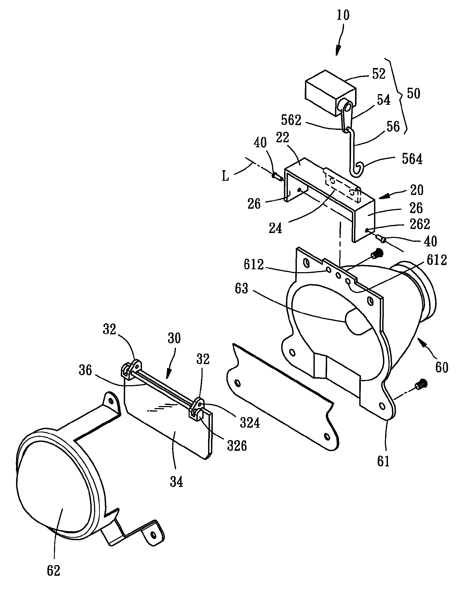
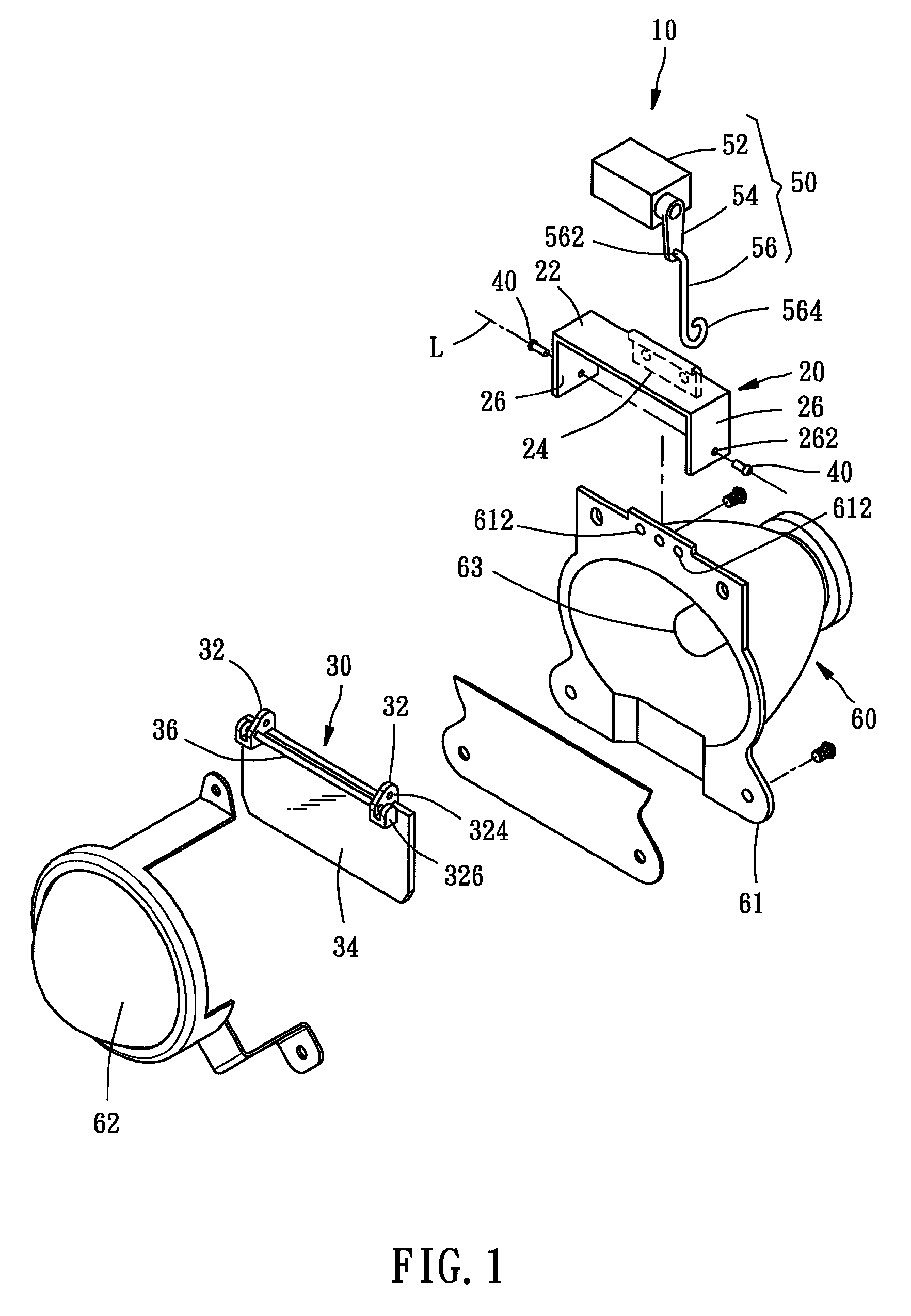
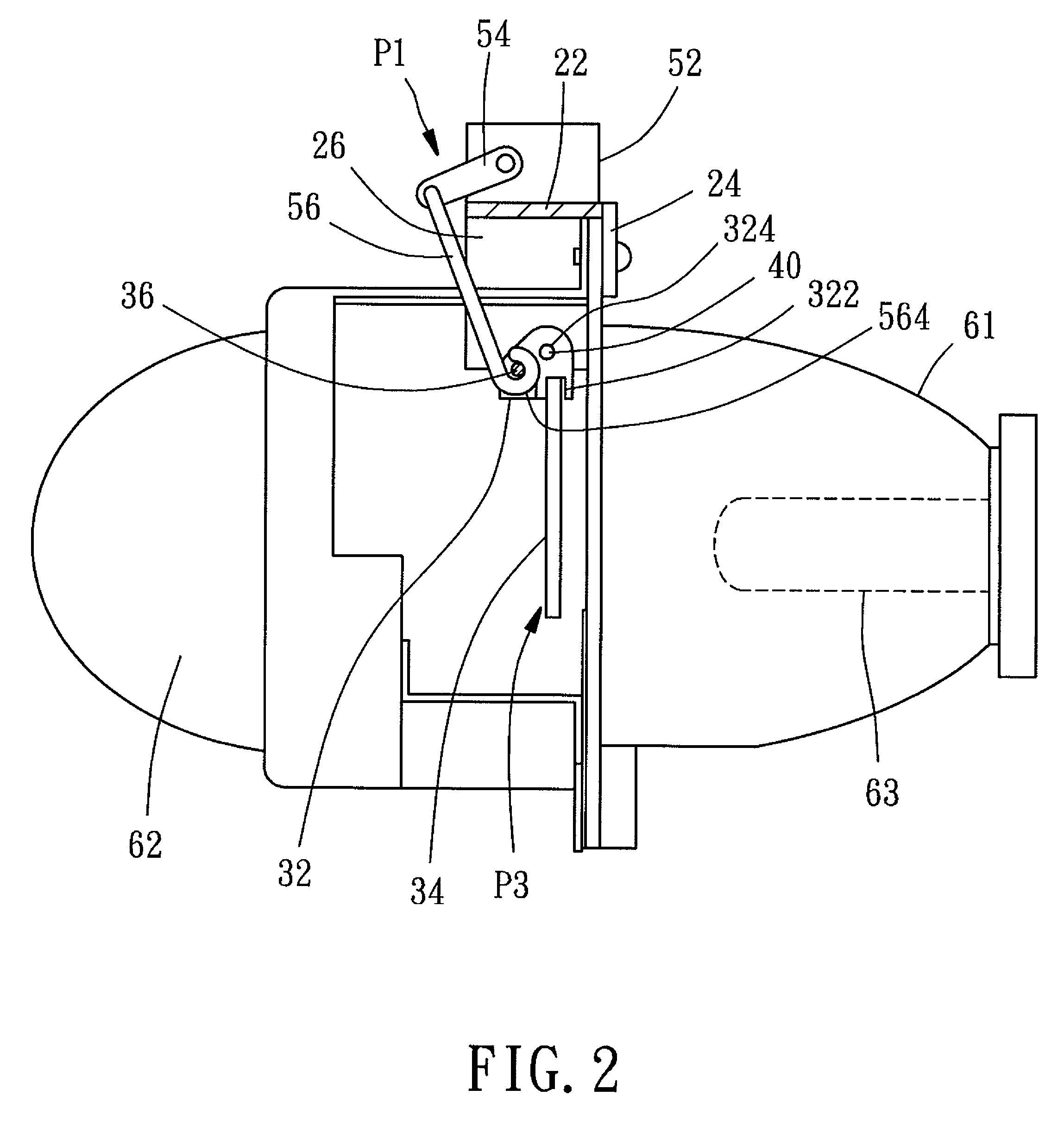
[0015]Referring to FIGS. 1-4, a vehicle lamp color-changing device 10 according to a preferred embodiment of the present invention comprises a bracket 20, a swinging unit 30, two pivots 40, and a rotary driving unit 50. The vehicle lamp color-changing device 10 is adapted to be installed in a vehicle lamp 60 and disposed between a base 61 and a lens 62 of the vehicle lamp 60. A light source 63 such as a bulb is disposed in the base 61 and emits lights toward the lens 62.

[0016]The bracket 20 has a tabulate supporting portion 22 disposed on a top of the base 61, a tabulate fastening portion 24 and two tabulate pivotal connecting portions 26 extending from the supporting portion 22 toward a same direction (downward in this embodiment). The fastening portion 24 is fastened to the base 61 by means of two screws (not shown) that are threadedly fixed in two fastening holes 612. Each of the pivotal connecting portions 26 has a threaded hole 262.

[0017]The swinging unit 30 comprises two holde...


PUM


Abstract

A vehicle lamp color-changing device includes a bracket, a swinging unit mounted to the bracket and swingable about an imaginary axis, and a rotary driving unit. The swinging unit includes a colored lens and an eccentric member disposed offset from the imaginary axis. The rotary driving unit has a rotary drive mounted to the bracket, a swingable arm connected with the rotary drive, and a pulling rod connected with the swingable arm and the eccentric member pivotally. In this way, the swingable arm is drivenable by the rotary drive to drive the pulling rod to move the eccentric member and thereby cause the swinging unit to swing in a way that the colored lens is swingable between an active position and an inactive position. As a result, the vehicle lamp color-changing device responds fast and is small-sized so as to be easily arranged in the vehicle lamp.

Description

BACKGROUND OF THE INVENTION[0001]1. Field of the Invention[0002]The present invention relates generally to vehicle lamp color-changing devices and more particularly, to a vehicle lamp color-changing device with a swingable arm.[0003]2. Description of the Related Art[0004]Taiwan Patent No. M461734 disclosed a rotary color-temperature-changing device for a lamp, which comprises a base for installation of a light source, a rotary mechanism installed on the base, and a colored lens attached to and driven by the rotary mechanism so that the color of lights emitted by the lamp is changeable by rotation of the colored lens. That is, the light color of the lamp is either the original light color of the light source or the color of light from the light source after projecting through the colored lens and thereby being changed in color temperature thereof.[0005]However, for the purpose of spacial arrangement, the aforesaid rotary color-temperature-changing device for a lamp uses a set of beve...

Claims


Application Information

Patent Timeline
Patent Type & Authority Patents(United States)
IPC IPC(8): F21S8/10B60Q3/00F21W107/10
CPCF21S48/1721B60Q3/001F21S48/1131F21S48/1225F21S48/1778F21S48/2206B60Q3/85F21S41/125F21S41/285F21S41/635F21S41/689F21S43/27
Inventor CHIANG, NAN-HSIN
Owner CHIANG NAN HSIN
Learn More