Differential signal transmission cable, multiwire differential signal transmission cable, and differential signal transmission cable producing method and apparatus

a technology of differential signal transmission and differential signal, which is applied in the direction of insulated conductors/cables, cables, cables, etc., can solve the problems of skewing or rapid signal attenuation, and the signal may also be attenuated. rapid, the effect of reducing the signal

Active Publication Date: 2015-09-15
HITACHI METALS LTD
View PDF20 Cites 20 Cited by
  • Summary
  • Abstract
  • Description
  • Claims
  • Application Information

AI Technical Summary

Benefits of technology

[0009]The inventors have found out that when the tapes are doubly wound around the shield tape, a gap is likely to occur between the insulation and the shield tape and / or in the overlapped portions of the shield tape, and have found that the occurrence of the gap can be suppressed by suppressing pivots of the conductors, the insulation, and the shield tape when the tapes are doubly wound therearound.
[0038]According to the invention, it is possible to suppress the occurrence of a gap between the insulation, which coats the pair of differential signal transmission conductors, and the shield tape conductor, and the occurrence of a gap in the overlapped portions of the longitudinally wrapped shield tape conductor.

Problems solved by technology

In the differential signal transmission cable thus configured, the occurrence of an unintended gap between the insulation and the shield tape causes a skew that is a signal propagation delay time difference between the pair of conductors, or rapid signal attenuation in a high frequency band (e.g. 10 Gbps or higher).
When the shield tape is longitudinally wrapped in such a manner that both ends in a width direction of the shield tape are overlapped together, a skew or rapid signal attenuation may also occur due to property variation caused by the occurrence of a gap in the overlapped portions between both the ends.

Method used


Image

  • Differential signal transmission cable, multiwire differential signal transmission cable, and differential signal transmission cable producing method and apparatus
  • Differential signal transmission cable, multiwire differential signal transmission cable, and differential signal transmission cable producing method and apparatus
  • Differential signal transmission cable, multiwire differential signal transmission cable, and differential signal transmission cable producing method and apparatus

Examples


embodiment

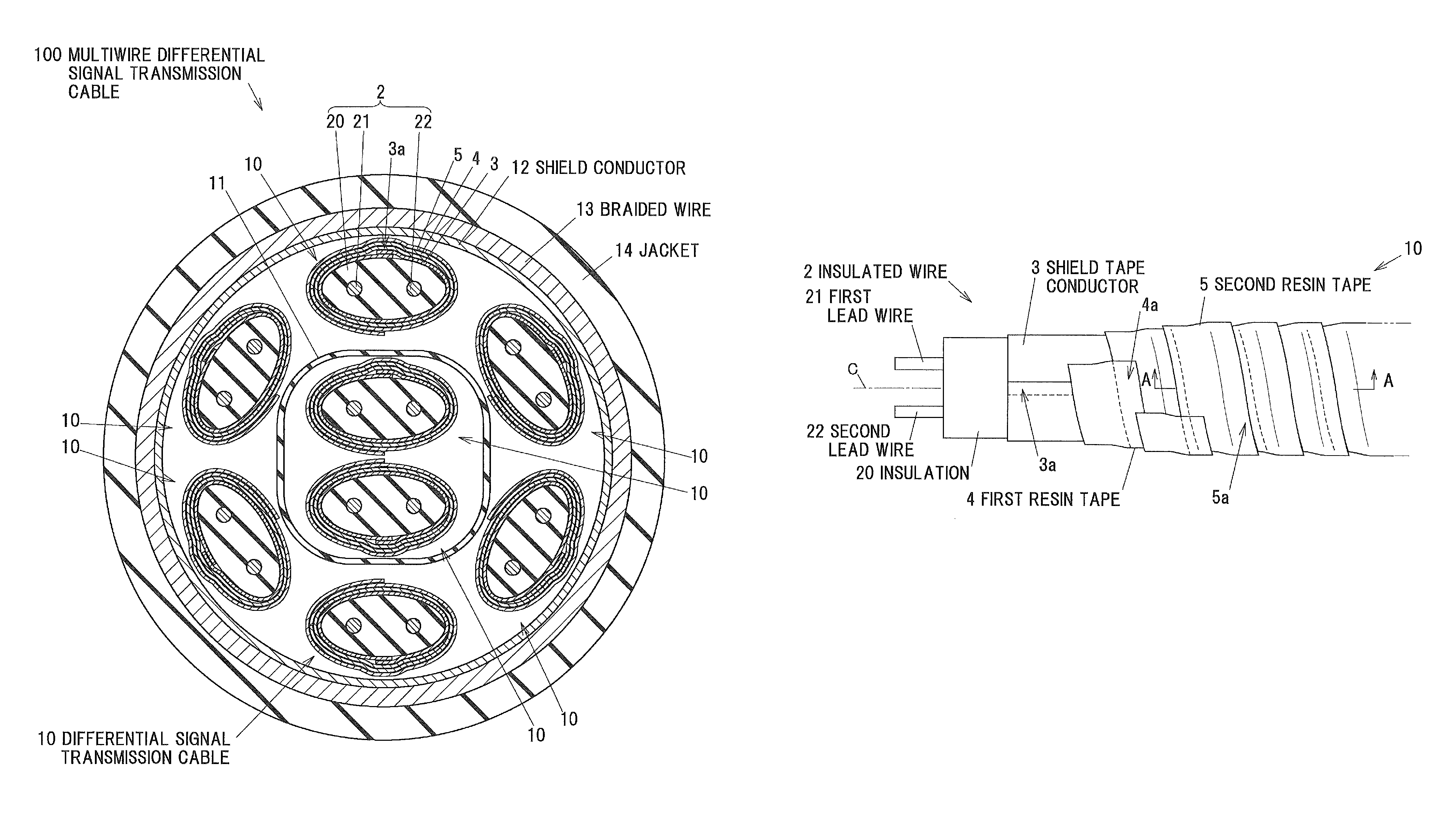
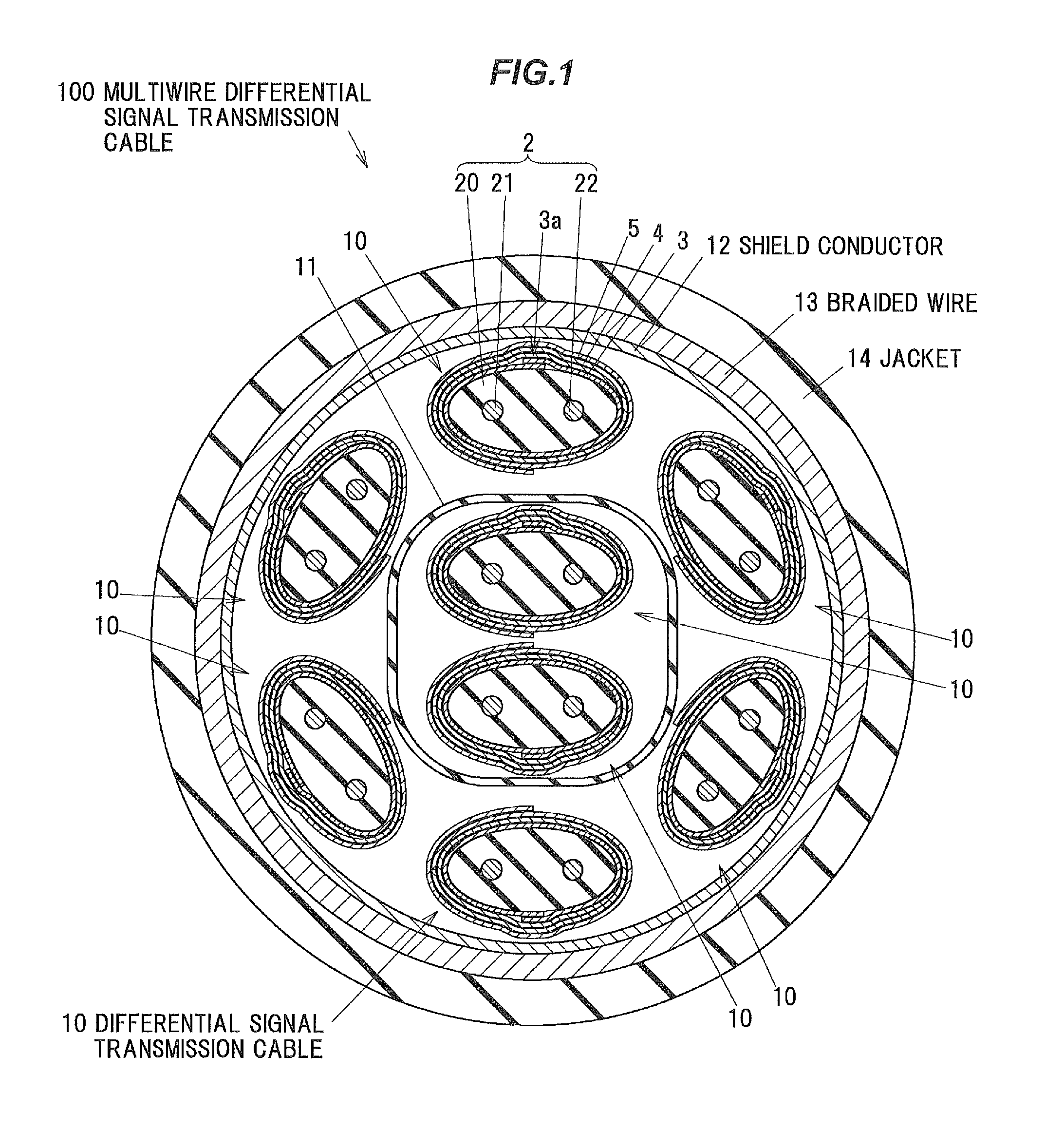
[0051]FIG. 1 is a cross-sectional view showing a cross-sectional structure of a multiwire differential signal transmission cable 100 including a plurality of differential signal transmission cables 10 in an embodiment according to the invention.

[0052]This multiwire differential signal transmission cable 100 is configured so that the plurality of differential signal transmission cables 10 (in the example shown in FIG. 1, eight differential signal transmission cables 10) are bundled together, and these bundled plural differential signal transmission cables 10 are shielded together with a shield conductor 12, and a perimeter of the shield conductor 12 is further covered with a braided wire 13, and these plural differential signal transmission cables 10, shield conductor 12 and braided wire 13 are received in a flexible jacket 14 made of an insulation.

[0053]Also, in the example shown in FIG. 1, two of the differential signal transmission cables 10 are disposed in a central portion of th...


PUM

PropertyMeasurementUnit
thicknessaaaaaaaaaa
thicknessaaaaaaaaaa
thicknessesaaaaaaaaaa

Abstract

A differential signal transmission cable includes an insulated wire including a pair of differential signal transmission conductors coated with an insulation, a shield tape conductor made of a band-like member including an electrically conductive metal layer, and wrapped along an outer surface of the insulated wire so that its ends in a width direction are overlapped together, a first resin tape spirally wound along an outer surface of the shield tape conductor and around an outer side of the shield tape conductor, and a second resin tape spirally wound along an outer surface of the first resin tape and around an outer side of the first resin tape. The shield tape conductor, the first resin tape and the second resin tape are wound in a same circumferential direction around a center axis of the insulated wire.

Description

[0001]The present application is based on Japanese patent application No. 2012-169905 filed on Jul. 31, 2012, the entire contents of which are incorporated herein by reference.BACKGROUND OF THE INVENTION[0002]1. Field of the Invention[0003]This invention relates to a differential signal transmission cable, a multiwire differential signal transmission cable, a differential signal transmission cable producing method and apparatus.[0004]2. Description of the Related Art[0005]Conventionally, differential signal transmission cables with a pair of differential signal transmission conductors coated with an insulation have been known. Some differential signal transmission cables of this type are wrapped with an electrically conductive shield tape around an insulation. (Refer to U.S. Pat. No. 7,790,981, for example.)[0006]The differential signal transmission cable disclosed by U.S. Pat. No. 7,790,981 has a pair of conductors coated with an insulation, and this insulation is wrapped with the ...

Claims


Application Information

Patent Timeline
Patent Type & Authority Patents(United States)
IPC IPC(8): H01B7/00H01B11/00H01B13/00H01B13/08H01B11/18H01B11/20
CPCH01B11/00H01B11/1869H01B13/00H01B13/0841H01B11/1826H01B11/20Y10T29/49117
Inventor SUGIYAMA, TAKAHIRONONEN, HIDEKIHAYASHI, HIROAKI
Owner HITACHI METALS LTD
Why Eureka
Try Eureka