

Sensor adapter cable
a technology of adapter cable and sensor, which is applied in the direction of diagnostic recording/measuring, application, coupling device connection, etc., can solve the problem that the solution cannot affect the ability of each of the spo2 technologies to operate correctly
- Summary
- Abstract
- Description
- Claims
- Application Information
AI Technical Summary
Benefits of technology
Problems solved by technology
Method used
Image

Examples
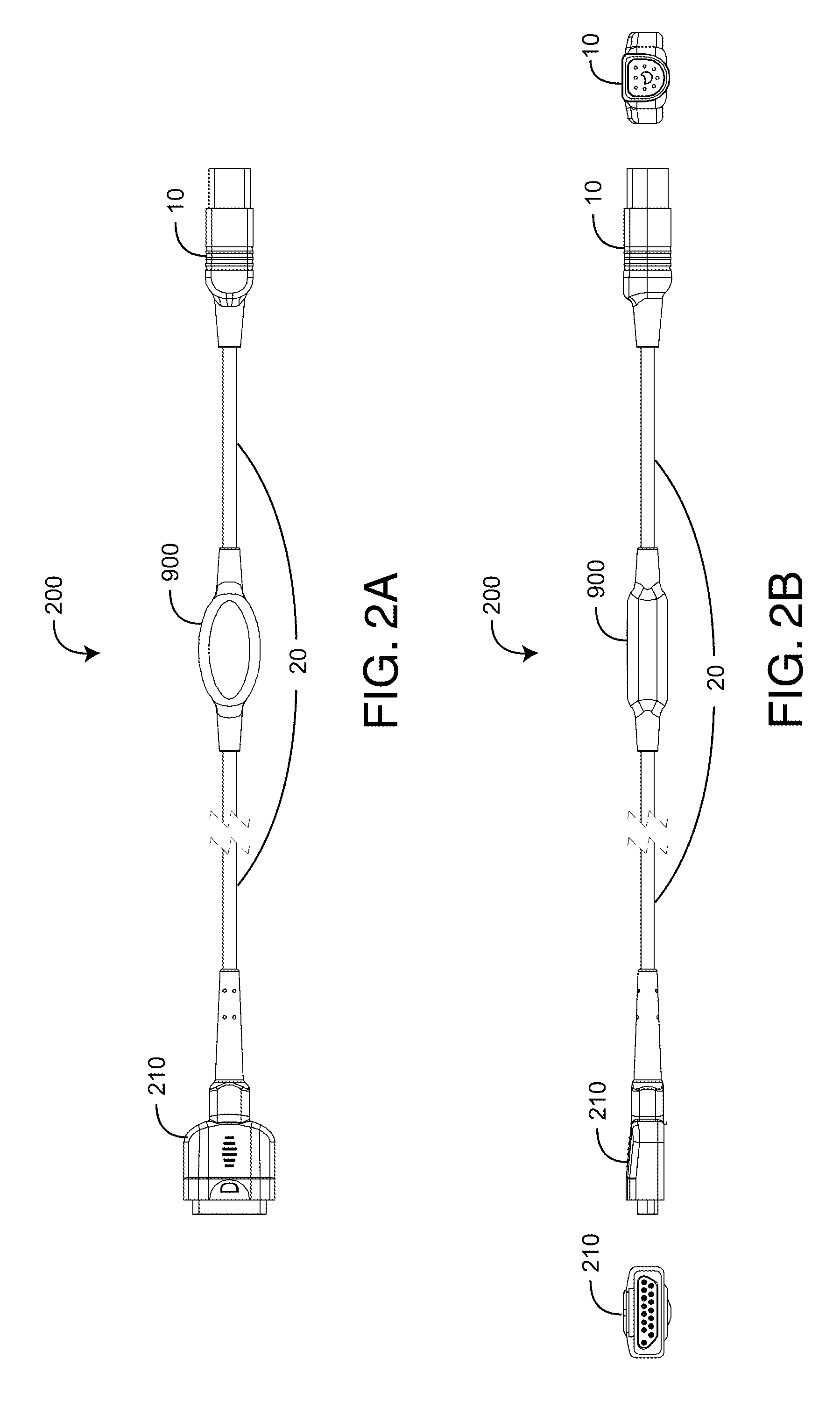
embodiment 200
[0027]FIGS. 3A-C further illustrate a sensor adapter cable embodiment 200, showing the respective pinouts of the M15 connector 210 and the D8 connector 10. Also shown are the corresponding cable 20 color-coded wires, inner shield and outer shield. Further shown is a sensor adapter circuit 400 and its connections relative to the connectors 10, 210 and cable 20 wires.
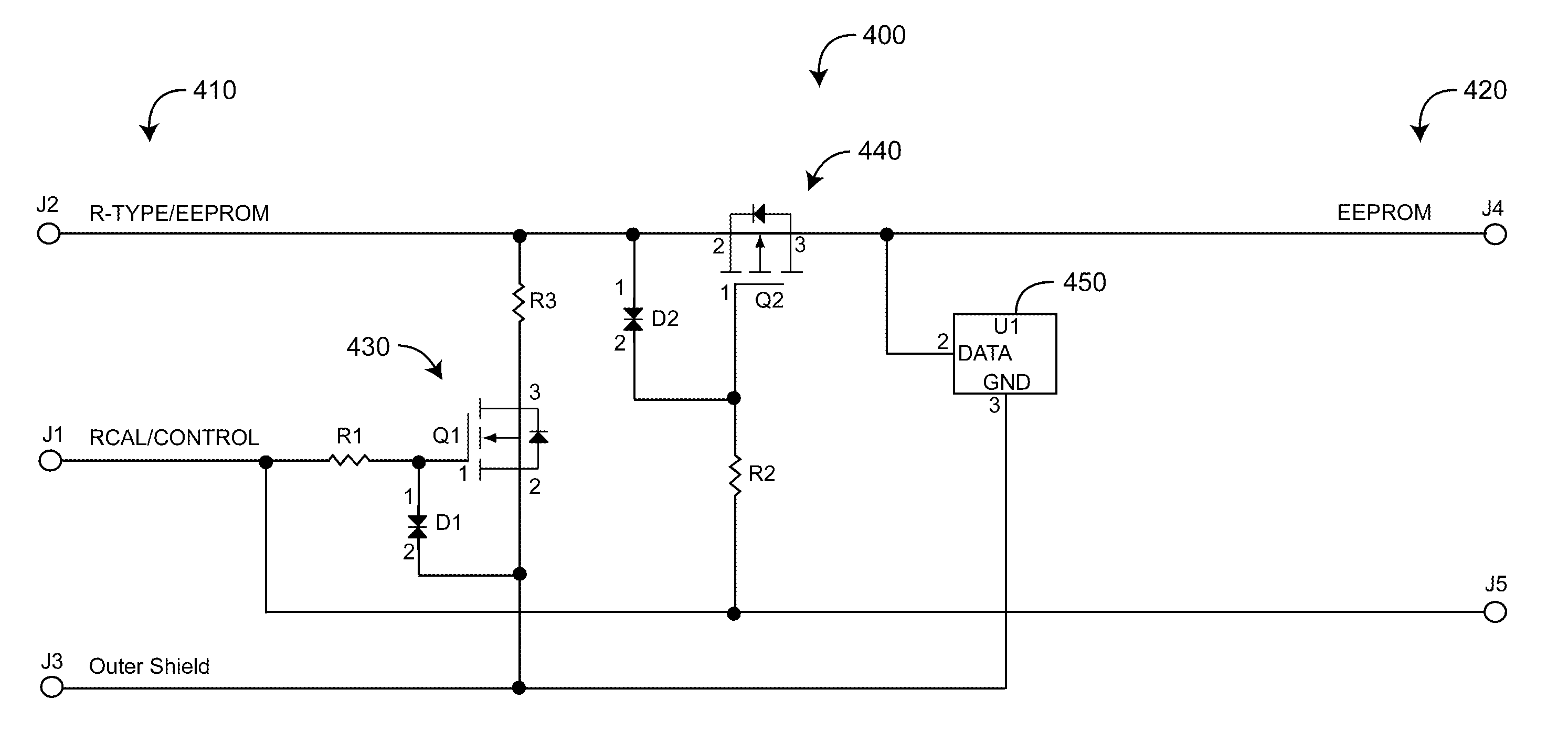
[0028]FIG. 4 illustrates the sensor adapter circuit 400 having plug-in connections 410 and sensor connections 420. The plug-in connections 410 (J1, J2, J3) connect to the plug-in connector 10 (FIGS. 2-3, 5-6, 7-8). The sensor connections 420 (J4, J5) connect to the sensor connector 210 (FIGS. 2-3); 510 (FIG. 5-6) or 710 (FIGS. 7-8). Table 1 below defines the signal names and associated connections to the plug-in connector pins.
[0029]
TABLE 1Adapter Circuit and Plug-in Connector PinoutsReferenceSignal NameDesignationPlug-in Connector Pin #R-TYPE / EEPROMJ23RCAL / CONTROLJ14OUTER SHIELDJ37
[0030]The switch components 430, 440 use...
embodiment 500
[0035]FIGS. 6A-C further illustrate a sensor adapter cable embodiment 500, showing the respective pinouts of the MC8 connector 510 and the D8 connector 10. Also shown are the corresponding cable 20 color-coded wires, inner shield and outer shield. Further shown are the sensor adapter circuit 400 connections relative to the connectors 10, 510 and cable 20 wires.
embodiment 700
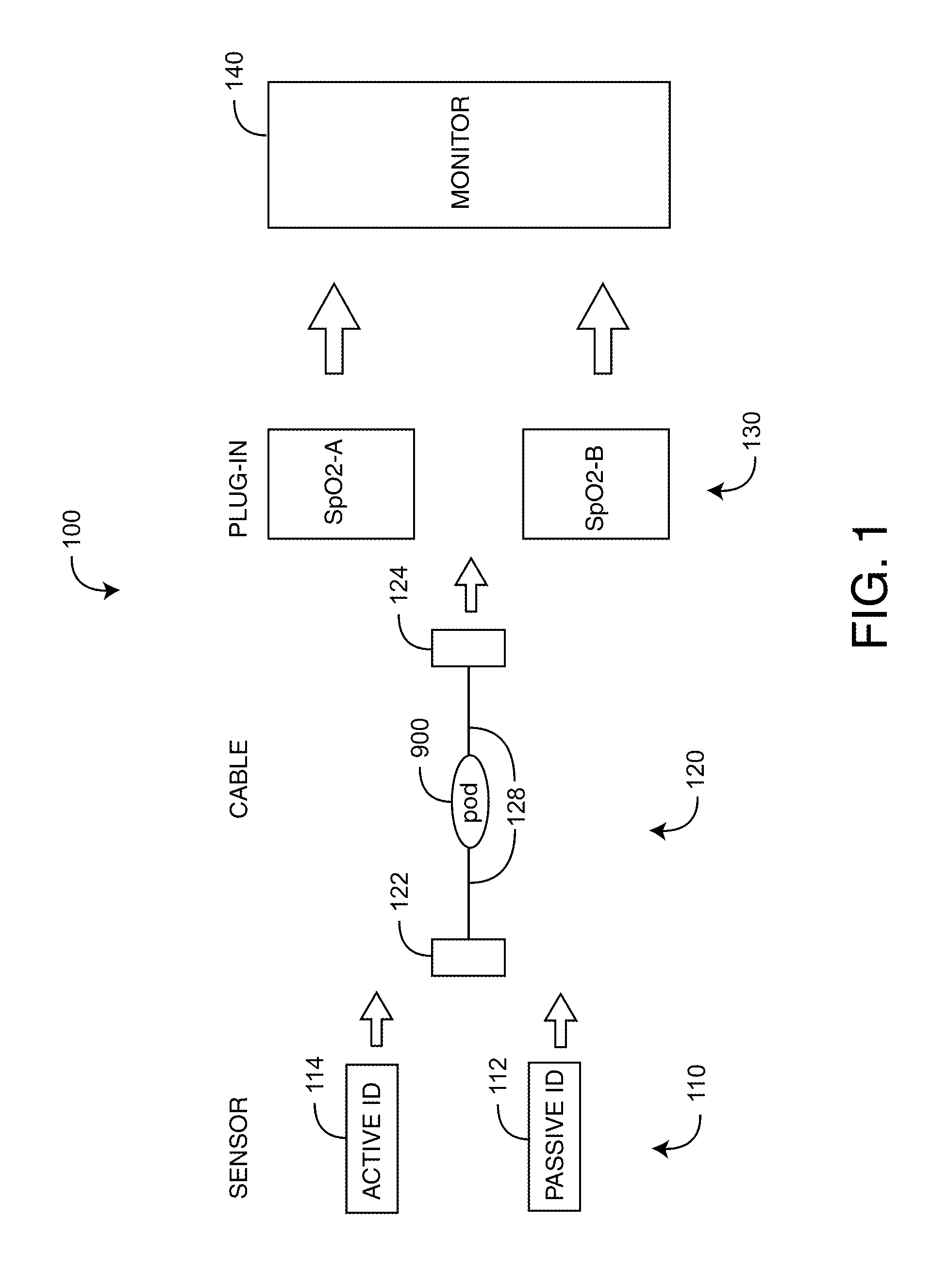
[0036]FIGS. 7A-B illustrate a sensor adapter cable embodiment 700 employing a DB9 sensor connector 710 and a D8 plug-in connector 10. A cable 20 interconnects the sensor connector 710 and the plug-in connector 10. A pod 900 integrated with the cable 20 contains a sensor adapter circuit 400 (FIG. 4) that insures electrical compatibility between a passive and an active ID 110 (FIG. 1) and a particular plug-in 130 (FIG. 1).
[0037]FIGS. 8A-C further illustrate a sensor adapter cable embodiment 700, showing the respective pinouts of the DB9 connector 710 and the D8 connector 10. Also shown are the corresponding cable 20 color-coded wires, inner shield and outer shield. Further shown are the sensor adapter circuit 400 connections relative to the connectors 10, 710 and cable 20 wires.
[0038]FIGS. 9A-B illustrate a pod 900 that splices the sensor adapter circuit 400 (FIG. 4) into the sensor adapter cable 20. The pod 900 has a overmold 910, a premold 920, a copper foil shield 930, a circuit bo...
PUM
 Abstract
Description
Claims
Application Information