Handheld work apparatus

a hand-held, work technology, applied in the direction of chainsaws, manufacturing tools, portable power-driven tools, etc., can solve the problems of high flow rate, and increased risk of dirt particles entering the housing, so as to prevent contamination of the control, clean cooling, and simple configuration

Active Publication Date: 2015-09-22
ANDREAS STIHL AG & CO KG
View PDF35 Cites 31 Cited by
  • Summary
  • Abstract
  • Description
  • Claims
  • Application Information

AI Technical Summary

Benefits of technology

[0008]Advantageously, the receptacle for the power supply unit is arranged in a region which faces away from the tool of the work apparatus. Clean cooling air can be drawn in from this region. The air inlet opening for the first cooling air flow is, in particular, situated closer to the tool than the receptacle of the power supply unit. Air which is more likely to be dirty is thus drawn in via the air inlet opening. In particular, a first gap, via which the second cooling air flow is drawn in, is formed between the power supply unit and the edge of the receptacle. As a result of the drawing-in via a gap, the penetration of dirt particles which are larger than the gap is constructively prevented. The second cooling air flow, in particular, serves to cool the control. Advantageously, the control has at least one cooling rib around which cooling air flows during operation. In this way, the control is cooled by air of the second cooling air flow which is more likely to be clean. Thus, contamination of the control is prevented.
[0009]Advantageously, the housing has an interior housing space in which the control is arranged. Thereby, the interior housing space is separated from the receptacle of the power supply unit, in particular, by an intermediate plate. Thus, a simple configuration is achieved. The intermediate plate can, for example, be part of a contact carrier of the power supply unit. The air inlet opening for the first cooling air flow advantageously leads into the interior housing space. In the typical working position of the work apparatus, the control is arranged above the air inlet opening for the first cooling air flow. If the first cooling air flow is partially redirected to the control, then it must flow upward, whereby any heavier dirt particles may fall downward. As a result of the redirection and the upward flow, a partial cleansing of the first cooling air flow is achieved. This prevents larger dirt particles from reaching the control.
[0010]In particular, a second gap, through which the second cooling air flow flows into the interior housing space of the work apparatus, is formed between the intermediate plate and the housing wall of the housing. The second gap can be made simply without any additional means. Sealing of the intermediate plate relative to the housing wall can be omitted, so that a simple configuration results. Because the gap can extend over a large portion of the periphery of the intermediate plate, a long gap length and thus a comparatively large total area via which the second cooling air flow can pass from the receptacle into the interior housing space, will result. Thus, low flow velocities are achieved. The control is, in particular, arranged adjacent to a section of the second gap. The control is thus cooled mainly by the second, clean cooling air flow.

Problems solved by technology

With very large air inlet openings the risk that dirt particles can be drawn into the housing is increased.
With small air inlet openings, the movement of a large volume flow leads to high flow velocities and negative pressures which likewise can promote the drawing in of dirt particles.
In particular, the electronic control is sensitive to heat as well as dirt.

Method used


Image

  • Handheld work apparatus
  • Handheld work apparatus
  • Handheld work apparatus

Examples


Embodiment Construction

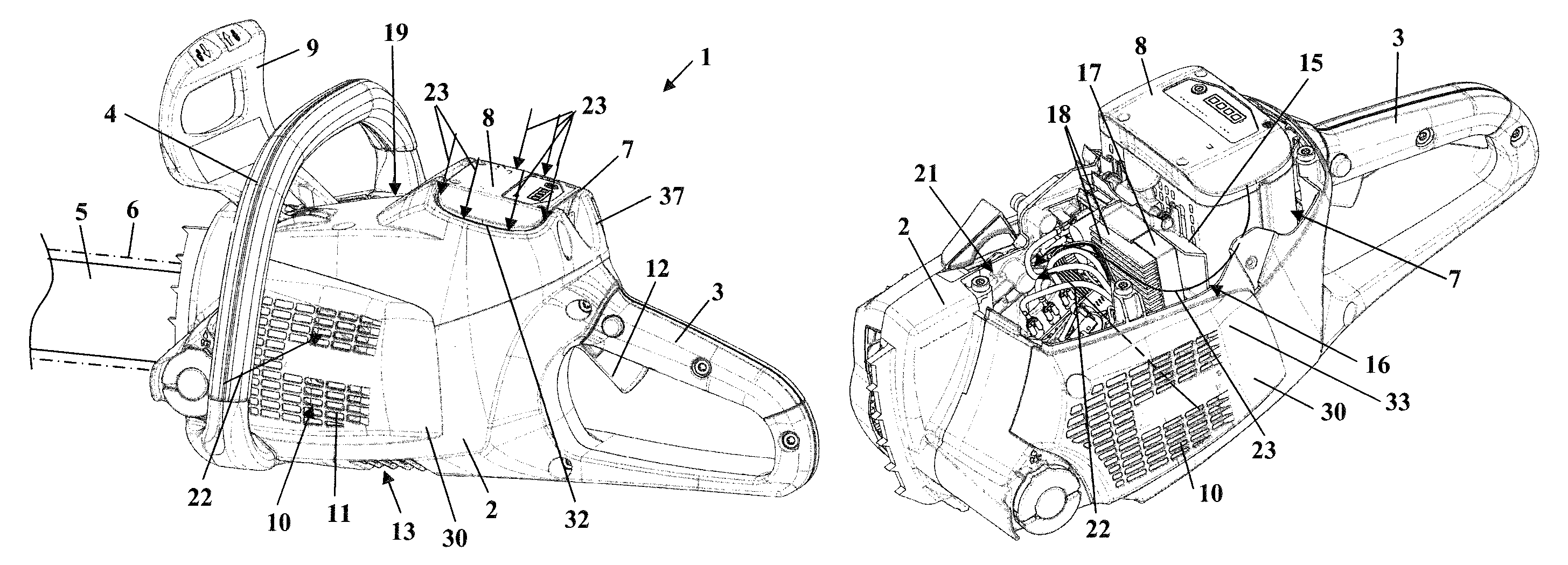
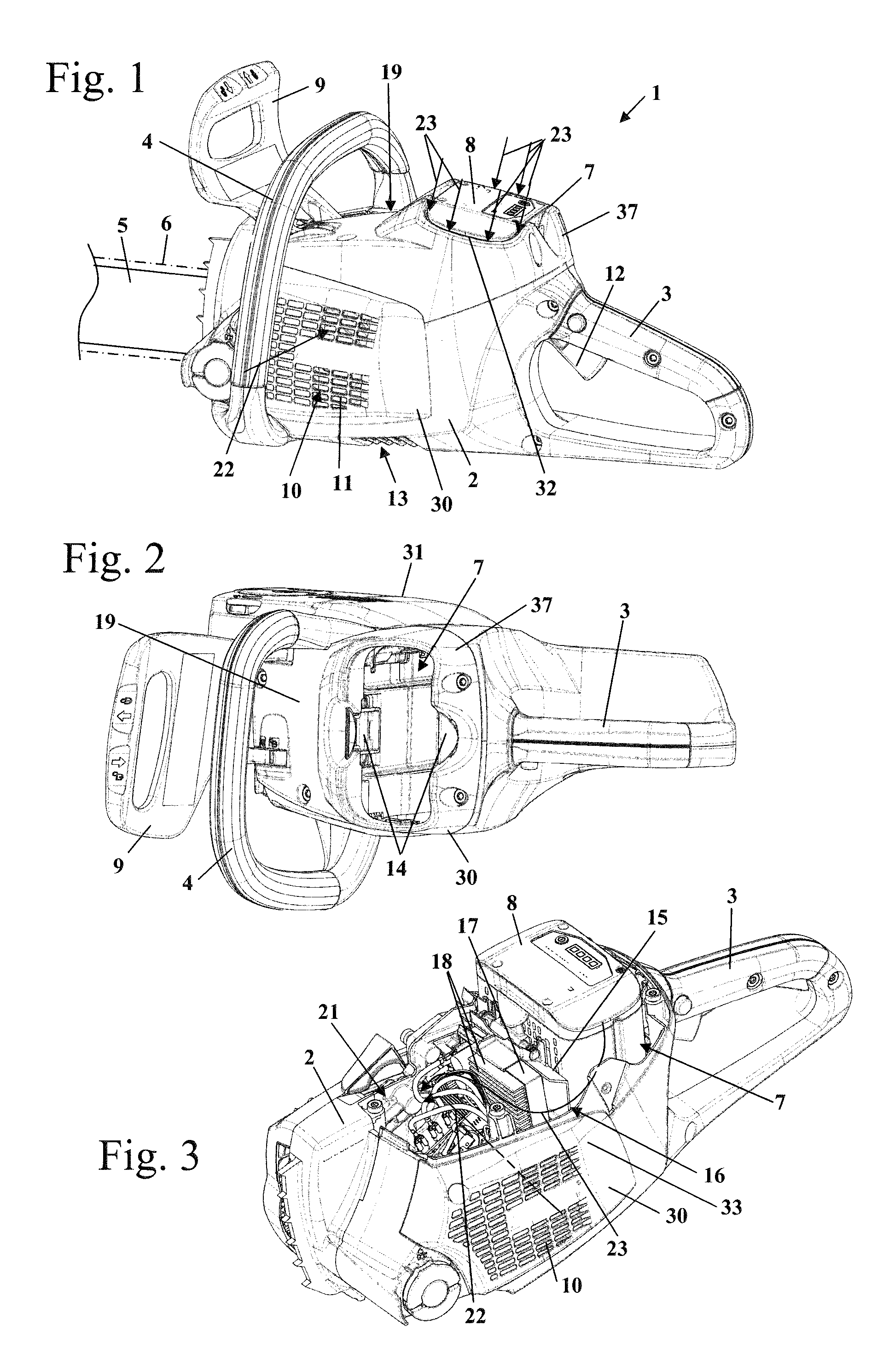
[0024]FIG. 1 shows a chain saw 1 as an embodiment of a handheld work apparatus. The chain saw 1 has a housing 2 which is closed on its top side 19 by a housing cover 37. FIG. 1 shows the chain saw 1 in the typical working position. In the typical working position, the top side 19 is arranged facing away from the ground. A rear handle 3 as well as a bale handle 4 are arranged on the housing 2. The bale handle 4 extends over the housing 2. The chain saw 1 has a guide bar 5 which projects forward and on which a saw chain 6 is driven in peripheral movement around the periphery. A hand guard 9 is arranged between the bale handle 4 and the guide bar 5.

[0025]A receptacle 7 is formed in the housing 2. A battery pack 8 is arranged in the receptacle 7 as a power supply unit. The receptacle 7 opens in the upward direction in the area of the housing cover 37. The receptacle 7 opens at the top side 19 of the housing in an area between the back handle 3 and the bale handle 4. A first gap 32 is fo...


PUM

PropertyMeasurementUnit
flow velocitiesaaaaaaaaaa
pressuresaaaaaaaaaa
distanceaaaaaaaaaa

Abstract

A handheld work apparatus has an electric drive motor (24) and a power supply unit for the drive motor (24). The power supply unit is arranged in a receptacle (7) of a housing (2) of the work apparatus. The work apparatus has an electronic control (17) and a blower wheel (29) for conveying cooling air. The blower wheel (29) is driven by a drive motor (24). The housing (2) has at least one air inlet opening (10) for cooling air via which the blower wheel (29) draws in a first cooling air flow (22) during operation. A second cooling air flow (23) is drawn into the housing (2) via the receptacle (7).

Description

CROSS REFERENCE TO RELATED APPLICATION[0001]This application claims priority of German patent application no. 10 2010 045 994.1, filed Sep. 18, 2010, the entire content of which is incorporated herein by reference.FIELD OF THE INVENTION[0002]The invention relates to a hand held work apparatus having an electric drive motor and a power supply unit for the drive motor.BACKGROUND OF THE INVENTION[0003]DE 10 2007 039 828 B3 discloses an electric machine tool having a blower and a battery. The electric machine tool is configured as a hammer drill and has air inlet openings in the rear housing region. The cooling air is drawn in through the housing in the direction of the battery via the motor arranged adjacent to the air inlet openings and exits the housing above the battery.[0004]In order to achieve sufficient cooling of the drive motor, a sufficient amount of cooling air must be conveyed through the housing. With very large air inlet openings the risk that dirt particles can be drawn i...

Claims


Application Information

Patent Timeline
Patent Type & Authority Patents(United States)
IPC IPC(8): B23Q11/14B25F5/00
CPCB25F5/008B23Q11/14
Inventor HEINZELMANN, GEORGLIEBHARD, GERNOTFORSTNER, DIRK
Owner ANDREAS STIHL AG & CO KG
Why Eureka
Try Eureka