Dual conveyor infeed for a header of an agricultural harvester

a technology of infeed and combine harvester, which is applied in the field of headers, can solve the problems of inconsistent flow of crop, interference of the outer end of the rotating infeed auger vanes, and negatively affecting the overall efficiency and operation of the combine during harvesting operations, so as to promote consistent conveyance and reduce crop left in the field

Active Publication Date: 2015-09-29
BLUE LEAF I P INC
View PDF18 Cites 12 Cited by
  • Summary
  • Abstract
  • Description
  • Claims
  • Application Information

AI Technical Summary

Benefits of technology

[0008]An advantage of headers constructed according to the subject application is that harvested grain is delivered to the feederhouse in a highly consistent manner regardless of the characteristics of the flow of grain being conveyed. That is, large and bushy crops as well as fine and thin crops can be conveyed to the feederhouse with equal effectiveness and with minimal resistance by the first and second infeed conveyors e.g., in a spread out evenly distributed manner across the entire width of the infeed conveyor. As a result, engine speed and other machine settings require less adjustment during operation of the harvester and less energy is consumed by the harvester. A further advantage of headers constructed according to the subject application is that grain and material other than grain (MOG) does not bunch up and collect at the lateral ends of the first and second infeed conveyors. Furthermore, the first and second infeed conveyors may be constructed and arranged so as to define a funnel-like mouth for simultaneously pulling the crop downwardly and rearwardly during conveyance. That is, the first and second conveyors define an inlet for receiving the flow of grain and an outlet for discharging the flow of grain. The inlet can be larger than the outlet for funneling the flow of grain from the inlet to the outlet. Consequently, crop is not deposited back onto the field and grain yield is correspondingly increased.

Problems solved by technology

It has been observed that during operation of an agricultural harvester having a header equipped with a feederhouse infeed auger that the outer ends of the rotating infeed auger vanes interfere with the laterally incoming crop flow.
This interference between the infeed auger vanes and the incoming crop flow causes crop to collect at the opposite ends of the infeed auger.
The collected crop in turn results in an inconsistent flow of crop being fed by the infeed auger to the feederhouse.
The inconsistent crop flow may include “dead zones” where little or no crop is present and is not actively being transported or moved and heavy zones where excessive crop is present.
Grain processed through the header can accumulate at the dead zones or voids and thereby negatively impact the overall efficiency and operation of the combine during harvesting operations.
Furthermore, in conventional combine harvesters, due to the overall cylindrical shape of the header's cross auger and the feederhouse feed drum, there exists a region or void space between them at or below their respective central rotational axes that grain is not actively transported.
Because of this void and lack of any active transport means between the cross auger and feeder drum grain flow may become inhibited and back up.
Such inconsistent crop flow results in inconsistent demands being placed on the entire harvesting machine.
Furthermore, some of the crop which collects at the outer ends of the infeed auger may be forced over the auger such that it is not picked up by the feederhouse conveyor and is left in the field, thereby resulting in a less than optimal crop harvest.

Method used


Image

  • Dual conveyor infeed for a header of an agricultural harvester
  • Dual conveyor infeed for a header of an agricultural harvester
  • Dual conveyor infeed for a header of an agricultural harvester

Examples


Embodiment Construction

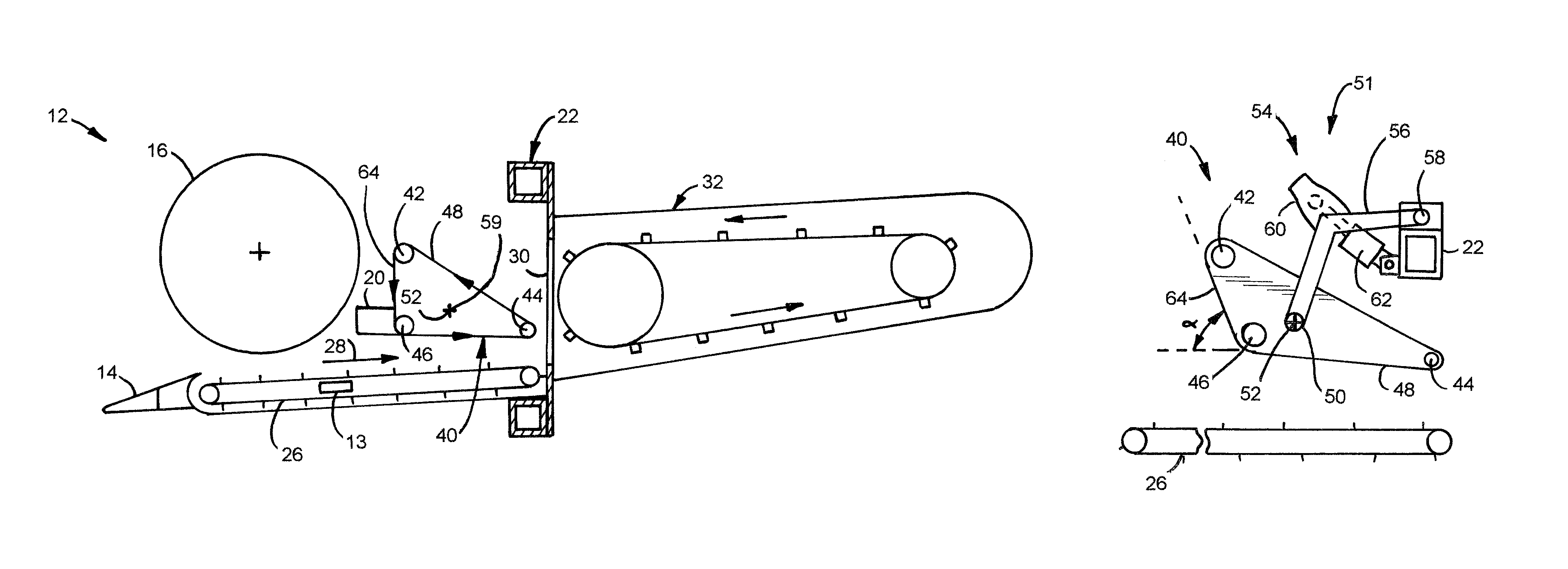
[0018]Reference will now be made in detail to the various aspects of the subject application illustrated in the accompanying drawings. Wherever possible, the same or like reference numbers will be used throughout the drawings to refer to the same or like features. It should be noted that the drawings are in simplified form and are not drawn to precise scale. In reference to the disclosure herein, for purposes of convenience and clarity only, directional terms such as top, bottom, left, right, above, below and diagonal, are used with respect to the accompanying drawings. Such directional terms used in conjunction with the following description of the drawings should not be construed to limit the scope of the subject application in any manner not explicitly set forth. Additionally, the term “a,” as used in the specification, means “at least one.” The terminology includes the words above specifically mentioned, derivatives thereof, and words of similar import.

[0019]The terms “grain” an...


PUM


Abstract

Improved headers of a combine harvester are disclosed. The headers include structure in the form of upper and lower infeed conveyors which cooperate to maintain compressive contact with a flow of crop material that is being conveyed by the belts to the header outlet regardless of the flow characteristics of the mat of material being conveyed. The result is a consistent flow of crop material being passed through the header which results in more efficient harvester operation and more productive crop yield.

Description

BACKGROUND[0001]The subject application relates generally to a header for use with agricultural harvesters. In particular, the subject application relates to a dual conveyor infeed for a header of a combine harvester.[0002]The headers for agricultural harvesters, such as combines, that harvest crops may assume a variety of configurations depending on the crop being harvested. In any case, harvester headers include devices for conveying harvested crop to a feederhouse after which the crop undergoes additional processing. After the crop is cut by a cutting knife or other cutting mechanism, it is typically gathered for example by a reel that transports the crop to a header conveyor device which may include one or more augers or belt conveyors. Generally, the header conveyor device includes an opposed set of lateral augers (as in an auger header) or belts (as in a draper header) which transfer crop from lateral ends of the header toward a feederhouse opening located at a central region ...

Claims


Application Information

Patent Timeline
Patent Type & Authority Patents(United States)
IPC IPC(8): A01D57/00A01D57/20A01D34/00
CPCA01D57/20A01D34/008A01D41/14
Inventor GAHRES, RYAN
Owner BLUE LEAF I P INC
Why Eureka
Try Eureka