Muscular evaluation and exercise device

a technology for evaluation and exercise, applied in the field of exercise devices, can solve problems such as limited value and be, however

Active Publication Date: 2015-09-29
CALDERONE MICHAEL P
View PDF11 Cites 8 Cited by
  • Summary
  • Abstract
  • Description
  • Claims
  • Application Information

AI Technical Summary

Benefits of technology

[0014]It is also an object of the present invention to provide a device for exercising upper body parts and muscles wherein the force required to operate the device can be varied by varying the amount of weight attached to the device.
[0015]It is another object of the present invention to provide an exercise device including a user manipulated counterbalanced elongate beam which enables independent variation of the degree beam imbalance about a center pivot by placement of free weights at each end of the beam, and independent variation of the overall mass of the beam by varying the aggregate number of free weights.
[0016]According to the preferred embodiment of the invention, the exercise device for therapeutic development of targeted user musculature include a base, a seat supported above the base by a vertically extending structure, a forearm pad adjustably disposed forward of the seat and supported above the base by an adjustable forearm pad support, an adjustably counterbalanced elongate beam assembly having a fore end portion extending forwardly of said seat, an aft end portion extending rearwardly of said seat, and a pivot interconnecting said beam assembly to said vertical seat structure while enabling rotational freedom of said beam assembly between first and second limits of travel, and lifting means pivotally attached to the fore end portion forward of said forearm pad.
[0017]According to another aspect of the invention, a second, infinitely adjustable weight assembly is carried on one or both end portions of the beam assembly. This arrangement enables precise selection of the beam's weight imbalance.

Problems solved by technology

They can be, however, of limited value in situations wherein the user is infirm, suffers from severe or chronic injuries, physical limitations, or is undertaking a medically supervised course of physical therapy.

Method used


Image

  • Muscular evaluation and exercise device
  • Muscular evaluation and exercise device
  • Muscular evaluation and exercise device

Examples


Embodiment Construction

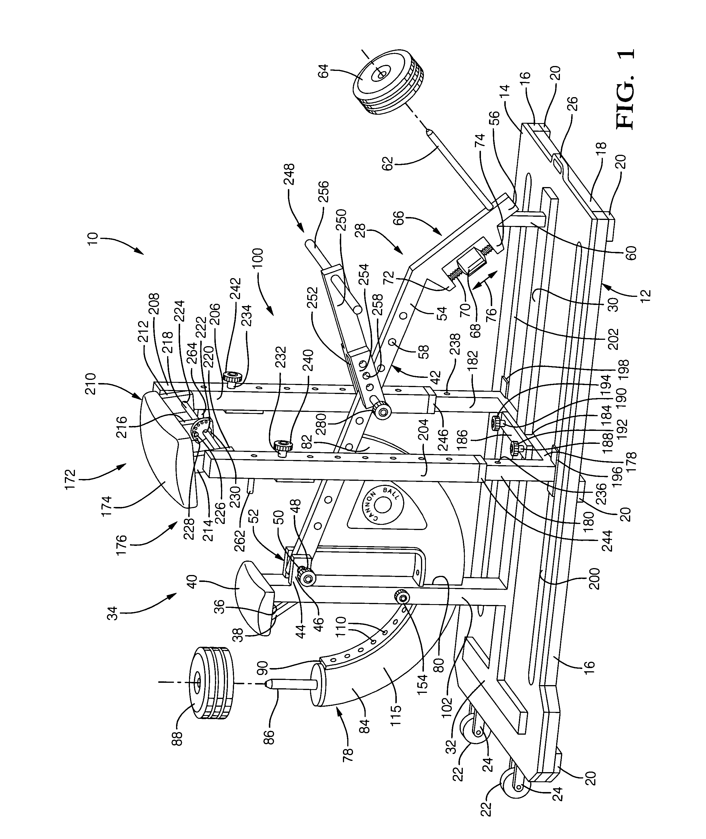
[0033]Referring to FIG. 1, a preferred embodiment of a muscular evaluation and exercise device 10 is illustrated. The exercise device 10 comprises a base assembly 12 of welded construction including a generally rectangular base plate 14, two longitudinally extending side members 16 and two laterally extending end members 18. The side and end members 16 and 18, respectively, serve to rigidify the base plate 14 and to elevate the base plate 14 above the floor (not illustrated) upon which it rests in application. The side and end members 16 and 18, respectively, are dimensioned and arranged to frame the perimeter of the base plate 14. The base plate 14 is preferably formed from slip-resistant material such as diamond steel plate. The side and end members 16 and 18, respectively, are preferably formed from square section steel tube.

[0034]In use, the exercise device 10 rests on a flat floor surface, and is prevented from inadvertent sliding movement thereon by resilient pads 20 mounted o...


PUM


Abstract

An apparatus for the development of upper body parts and muscles is disclosed. The apparatus includes a base on which is mounted a seat supported above the base and a forearm pad disposed forward of the seat and supported above the base. A pivoted lever is pivoted at a first end to a seat support, a second end of the lever extends past the forearm pad a distance and includes a weight supporting pin which extends vertically upward. A lifting device is selectively and pivotally attached to the pivoted lever forward of the forearm rest. A plurality of weights are selectively attached to the weight support pin to vary the amount of force required to use the lifting device and raise the weights. A variety of attachments are selectively affixed to the lifting device to exercise various body parts and muscles.

Description

TECHNICAL FIELD[0001]The present invention relates to the field of exercise devices, and more particularly the present invention relates to the field of exercise devices for developing targeted body parts and muscles. Even more particularly, the present invention relates to the field of exercise devices for medical application for objectively measuring the state of development of muscles of the shoulders, upper arms, forearms, wrists and back.BACKGROUND OF THE INVENTION[0002]A search of issued U.S. patents in the field of muscular exercising devices and apparatus reveals U.S. patents related generally to the field of the present invention but which do not anticipate nor disclose the device of the present invention. The discovered U.S. patents relating to the present invention are discussed herein below.[0003]U.S. Pat. No. 3,573,865 to Annas et al. entitled “Weight Shifting Mechanism for Exercising” discloses an exercise device wherein the user pushes against an arcuately movable ped...

Claims


Application Information

Patent Timeline
Patent Type & Authority Patents(United States)
IPC IPC(8): A63B21/062A63B21/012A63B21/06A63B21/00A63B23/035A61B5/103A63B23/12A63B71/00A63B71/02A61B5/22
CPCA63B21/0615A61B5/103A63B21/0125A63B23/03525A63B23/1209A63B23/1281A61B5/224A61B2505/09A63B23/1236A63B2021/0616A63B2071/0072A63B2071/025A63B2220/13A63B2220/16A63B2220/17A63B2220/24A63B2220/52A63B2230/01A63B21/0616
Inventor CALDERONE, MICHAEL P.
Owner CALDERONE MICHAEL P
Why Eureka
Try Eureka