
Electronic safe

a safe and electronic technology, applied in the field of safes, can solve the problems not everyone, and access by unauthorized individuals, and achieve the effect of increasing the risk of accidental discharg

Active Publication Date: 2015-09-29
LEBLANC WILLIAM A
View PDF24 Cites 17 Cited by
  • Summary
  • Abstract
  • Description
  • Claims
  • Application Information

AI Technical Summary

Benefits of technology

The invention is about an electronic wall safe with a body and door that can be opened easily with a user interface. The safe has a locking mechanism, cut wire detection system, and communication system that can send a signal to a preselected entity upon detecting a cut wire. These features provide increased security and allow for quicker opening in case of an emergency.

Problems solved by technology

While concealed handguns are helpful for this purpose, not everyone interested with the safety of children may be willing to carry a handgun on a daily basis.
Access by unauthorized individuals could potentially occur by unauthorized opening of a safe containing the firearms, or by theft of the safe containing the firearms, and resisting both is important.
Frequency administrative handling of the firearm could potentially increase the risk of an accidental discharge.
This gun safe fails to provide any means of communicating unauthorized access and / or theft, or any means of verifying its contents without opening the safe.
This gun safe fails to provide any means of verifying its contents without opening the safe.
The safe includes a low battery alarm and external emergency power. his gun safe fails to provide any means of verifying its contents without opening the safe.
When such a signal is received, the gun safe may perform any of several actions, including opening the door, switching to a simplified access code for opening the door, making opening the door more difficult, or deactivating the opening mechanism.
Although this safe provides for receiving signals from external devices, little is taught about providing communication to external entities.

Method used


Image

  • Electronic safe
  • Electronic safe
  • Electronic safe

Examples


Embodiment Construction

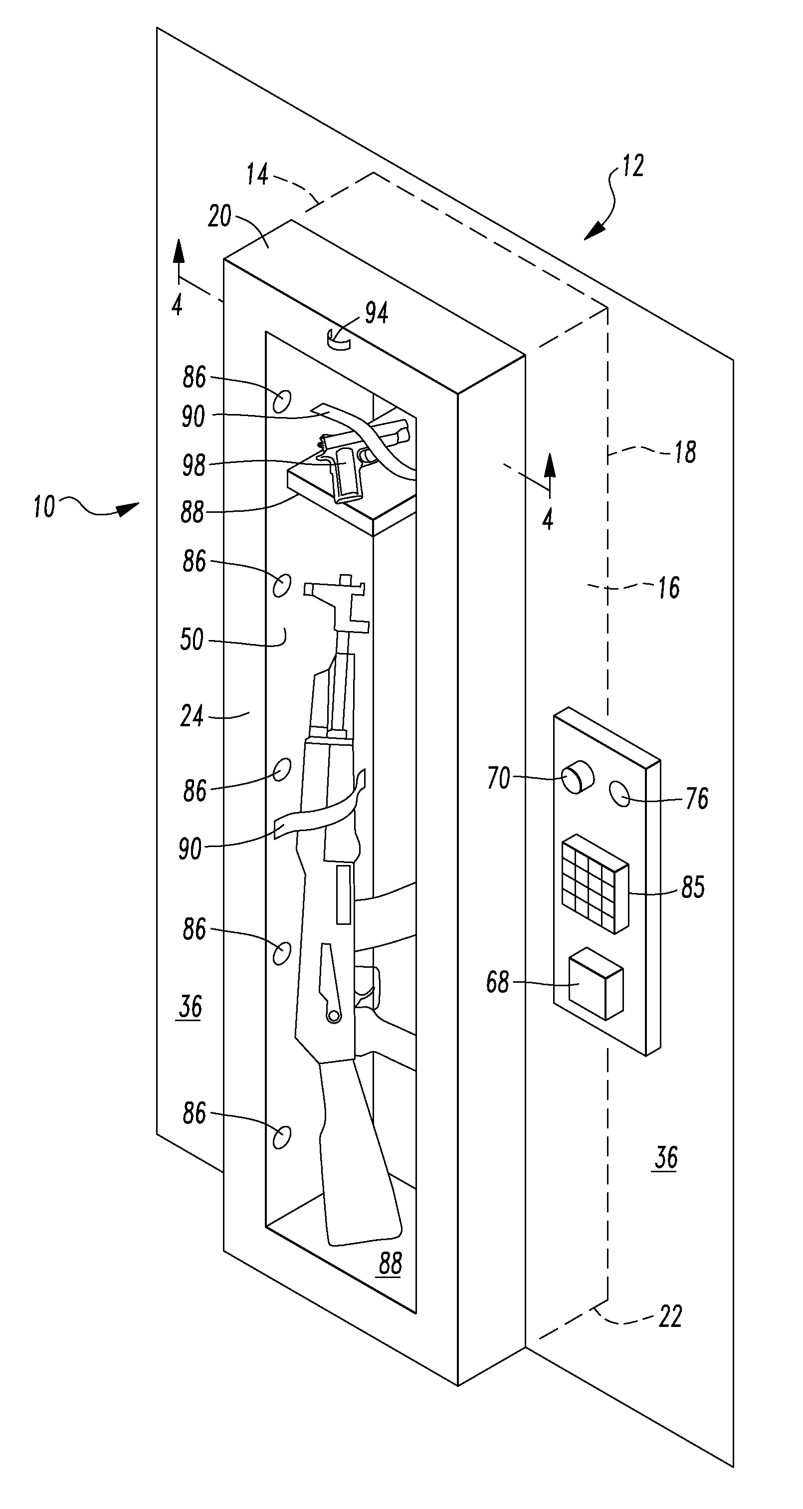
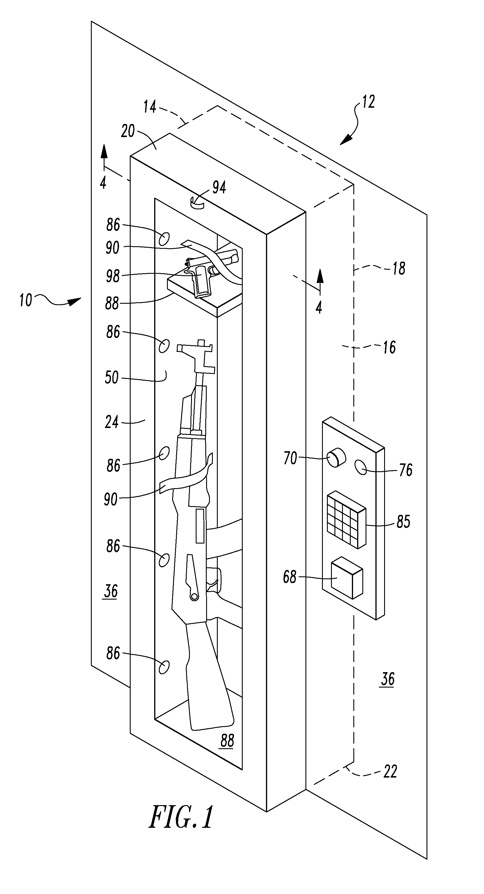
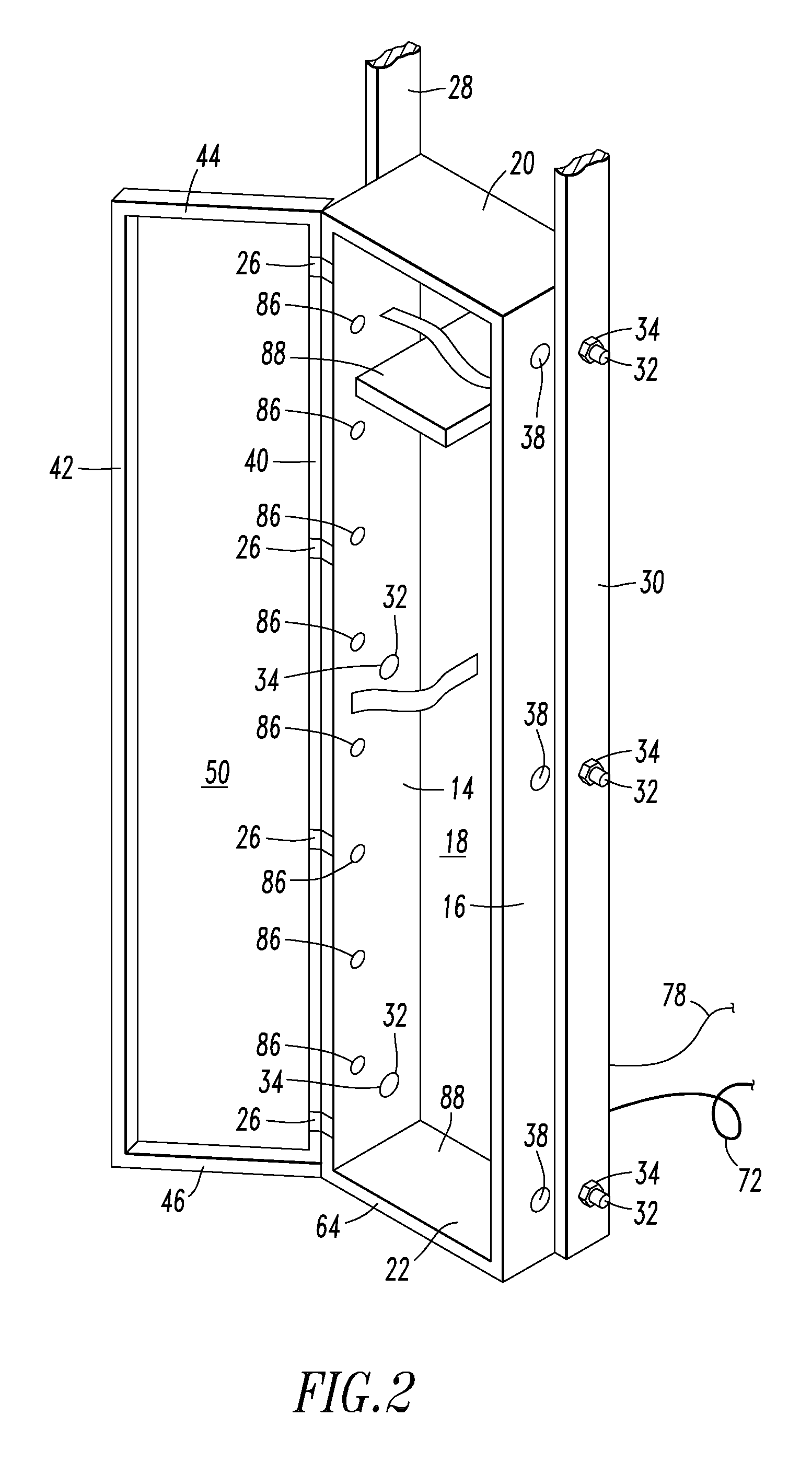
[0029]Referring to the drawings, an example of a safe 10 is illustrated. Although a wall safe is illustrated, the safe can be secured within floors, or against other generally planar building portions having adjacent building frame members such as wall “studs” or floor joists, or the like, without departing from the scope of the invention. Although the illustrated example of the safe 10 is sized to hold a modern sporting rifle, other sizes, such as those designed only to hold handguns, those designed to hold money and / or jewelry, or sizes designed to hold important papers, are all within the scope of the invention. Referring to FIGS. 1-2, the wall safe 10 includes a body 12 having a left side 14, right side 16, back 18, top 20, and bottom 22. A door 24 is hingedly attached to the body 12, in the illustrated example being hingedly attached to the left side 14 by internal hinges 26 (FIG. 2). The safe 10 is structured to be secured between the frame members or “studs”28, 30 (FIG. 2) wi...


PUM


Abstract

An electronic wall safe is intended to fit between the support beams of a typical building, bolting into the beams on either side of the safe. A panel is provided around the safe to prevent cutting into the wall to remove the safe. The safe includes numerous electronic features, which are powered by running an electrical wire to the safe, as well as battery backup. The CPU includes a connection for a telephone line, as well as wireless communication. The safe utilizes a fast-opening mechanism such as a fingerprint scanner. A panic button is provided to alert authorities and / or others on the premises of the emergency. The safe includes a mercury switch so that, if the safe is moved, then the opening mechanism will be disabled, and police will be notified. The safe includes cut wire detection circuitry. One possible variation of the safe includes a door having a shatter-resistant window, as well as internal lighting, so that the contents of the safe can be displayed or verified without opening the safe.

Description

CROSS REFERENCE TO RELATED APPLICATION[0001]This application claims the benefit of U.S. Provisional Patent Application No. 61 / 786,282, filed on Mar. 14, 2013, and entitled “Electronic Wall Safe.”TECHNICAL FIELD[0002]The present invention relates to safes. More specifically, an improved electronic wall safe is provided.BACKGROUND INFORMATION[0003]Firearms have been one of the most effective tools of self-defense almost since their initial invention. Responsible gun owners realize that firearms must not only be kept readily available, but also properly secured from unauthorized individuals. In particular, recent school shootings have revealed both the need to have firearms available to qualified, authorized personnel in order to protect children within the school. While concealed handguns are helpful for this purpose, not everyone interested with the safety of children may be willing to carry a handgun on a daily basis. Furthermore, some situations may best be handled with long guns s...

Claims


Application Information

Patent Timeline
Patent Type & Authority Patents(United States)
IPC IPC(8): E05B45/06E05G1/10E05G1/024
CPCE05G1/10E05G1/024
Inventor LEBLANC, WILLIAM A.
Owner LEBLANC WILLIAM A
Learn More