Burr resistant fastener-mounted bearing assembly

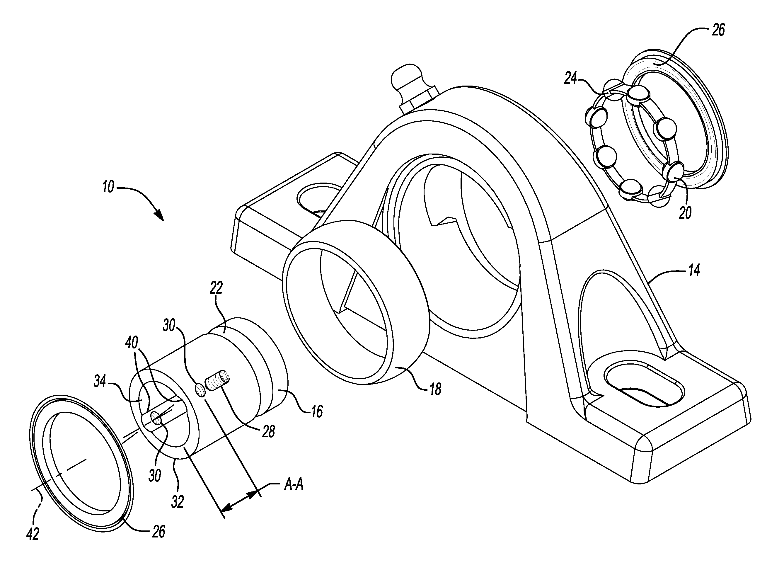
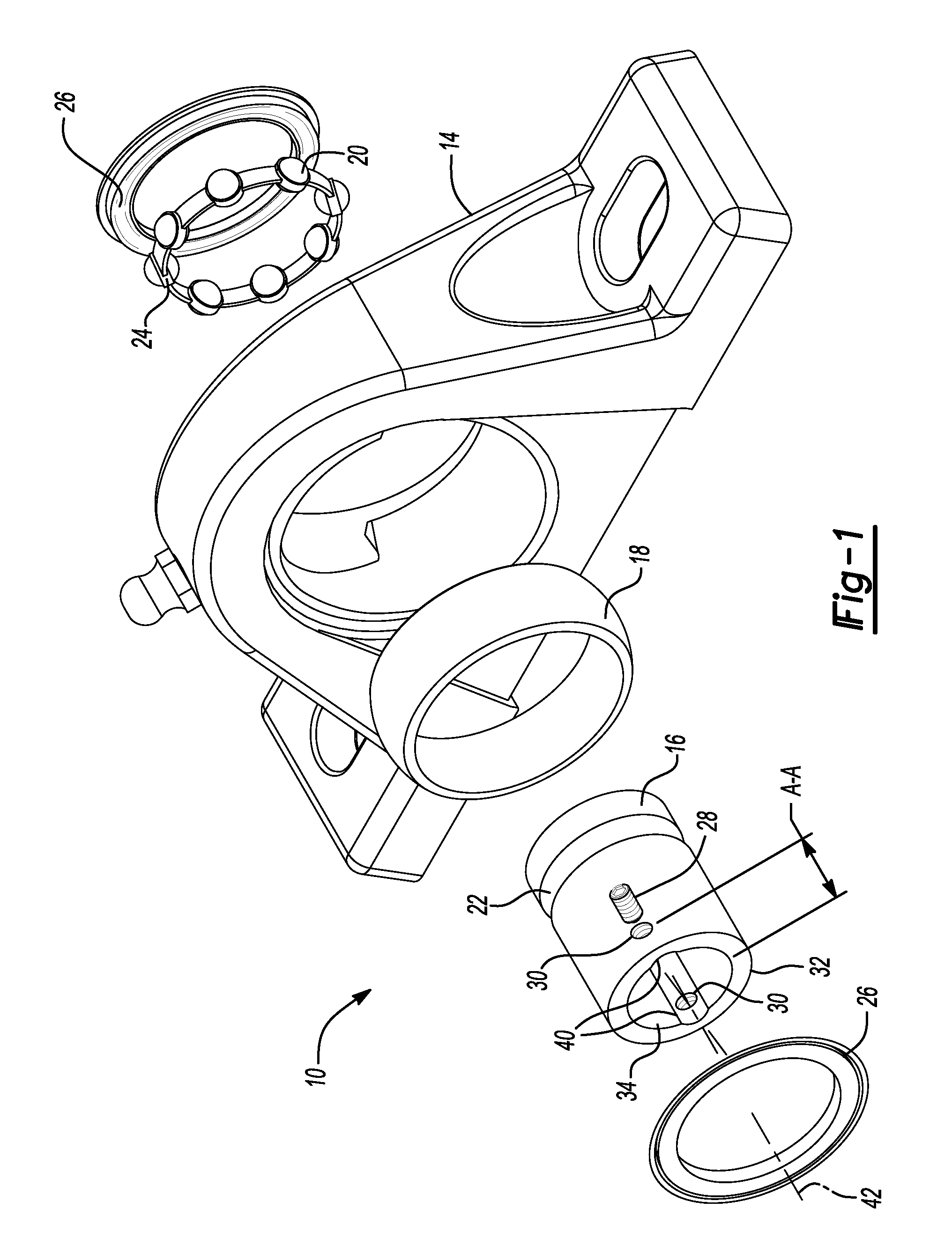
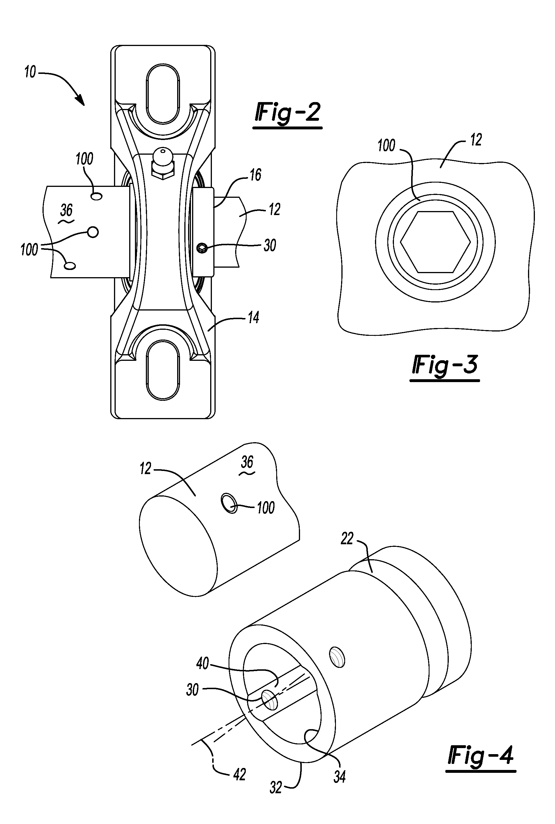
a technology of fastener and bearing assembly, which is applied in the direction of bearing components, rigid support of bearing units, shafts and bearings, etc., can solve the problems of burr or other rough edge or ridge left on the surface of the shaft, bearing assembly becoming stuck or otherwise physically joined, and potential damage to one or more shaft members and bearing assemblies, so as to facilitate the removal of inner ring 16 and eliminate potential stress concentrations.

Active Publication Date: 2015-09-29
REGAL BELOIT AMERICA
View PDF14 Cites 2 Cited by
  • Summary
  • Abstract
  • Description
  • Claims
  • Application Information

AI Technical Summary

Benefits of technology

[0003]In conventional fastener type bearing assemblies, a ring member is often secured to a shaft member using one or more fasteners, such as setscrews, disposed about the ring member. The fastener is a traditional threaded fastener that extends through the inner ring of the bearing assembly and engages the shaft member that is rotatably supported by the bearing assembly. The mechanical or frictional engagement of the fastener against the shaft member serves to retain the shaft member and inner ring of the bearing assembly in a coupled relationship.
[0006]According to principles of the present teachings, the bearing assembly is configured to minimize burr-related encumbrances between the inner ring and the shaft member for improved ease of removal.
[0030]In some embodiments, groove(s) 40 can define any one of a number of cross-sectional shapes capable of clearing burr 100. By way of non-limiting example, in some embodiments, groove(s) 40 can define an arcuate shape (see FIG. 4) to eliminate potential stress concentrations. In some embodiments, groove(s) 40 can define a channel shape or other cutout shape. It should be appreciated that the size, shape, and depth of groove(s) 40 should be selected so as not to negatively affect the heat treatment or shape of raceway 22 when mounted on shaft member 12. In some embodiments, groove(s) 40 is sized to permit slight rotation in a direction coaxial with the longitudinal axis of shaft member 12 to facilitate removal of inner ring 16 from shaft member 12.
[0031]According to the principles of the present teachings, several benefits and advantages are realized. By way of non-limiting example, the present teachings minimize burr-related encumbrances between the inner ring and the shaft member to permit a bearing user or operator to remove the inner ring from the shaft member without special tools or special knowledge regarding the burr. The present teachings can further provide benefits in minimizing the force and / or damage caused during the removal process of the inner ring from the shaft member.
[0032]Moreover, the groove(s) reduces the out-of-roundness of the raceway when mounted on the shaft. That is, it has been found that the use of groove(s) 40 as described herein can result in reduced out-of-roundness of the raceway 22 as compared to set screw mounted bearings without groove(s) 40.

Problems solved by technology

However, it has been found that the mechanical or frictional engagement of the fastener against the shaft can result in the formation of a burr or other rough edge or ridge left on the surface of the shaft.
Failure to do these steps typically results in the bearing assembly becoming stuck or otherwise physically joined to the shaft and potential damage to one or more of the shaft member and the bearing assembly.
This can contribute to downtime.

Method used


Image

  • Burr resistant fastener-mounted bearing assembly
  • Burr resistant fastener-mounted bearing assembly
  • Burr resistant fastener-mounted bearing assembly

Examples


Embodiment Construction

[0016]Example embodiments will now be described more fully with reference to the accompanying drawings.

[0017]Example embodiments are provided so that this disclosure will be thorough, and will fully convey the scope to those who are skilled in the art. Numerous specific details are set forth such as examples of specific components, devices, and methods, to provide a thorough understanding of embodiments of the present disclosure. It will be apparent to those skilled in the art that specific details need not be employed, that example embodiments may be embodied in many different forms and that neither should be construed to limit the scope of the disclosure. In some example embodiments, well-known processes, well-known device structures, and well-known technologies are not described in detail.

[0018]The terminology used herein is for the purpose of describing particular example embodiments only and is not intended to be limiting. As used herein, the singular forms “a,”“an,” and “the” ...


PUM


Abstract

A bearing assembly for rotatably supporting a shaft member. The bearing assembly has an inner ring having an inner surface sized to receive the shaft member therein. A first fastener threadedly engages a first fastener aperture formed in the inner ring such that a distal end of the first fastener engages the shaft member to selectively retain the inner ring to the shaft member for rotation therewith. A first groove extends along the inner surface of the inner ring and is aligned with the first fastener aperture formed in the inner ring. The first groove is sized to permit clearance between a burr or other obstruction formed on an exterior surface of the shaft member.

Description

FIELD[0001]The present disclosure relates to bearing assemblies and, more particularly, relates to bearing assemblies having a fastener-mounted bearing assembly.BACKGROUND AND SUMMARY[0002]This section provides background information related to the present disclosure which is not necessarily prior art. This section further provides a general summary of the disclosure, and is not a comprehensive disclosure of its full scope or all of its features.[0003]In conventional fastener type bearing assemblies, a ring member is often secured to a shaft member using one or more fasteners, such as setscrews, disposed about the ring member. The fastener is a traditional threaded fastener that extends through the inner ring of the bearing assembly and engages the shaft member that is rotatably supported by the bearing assembly. The mechanical or frictional engagement of the fastener against the shaft member serves to retain the shaft member and inner ring of the bearing assembly in a coupled relat...

Claims


Application Information

Patent Timeline
Patent Type & Authority Patents(United States)
IPC IPC(8): F16C35/063F16C33/58F16C35/04
CPCF16C33/586F16C35/047F16C35/062F16C35/063F16C35/07F16D1/0847
Inventor PHILLIPS, SCOTT W.HOFFMANN, KIM D.
Owner REGAL BELOIT AMERICA
Why Eureka
Try Eureka