Portable media equipment support device with rotating action

Inactive Publication Date: 2015-09-29
SWANSON BENJAMIN ALEXANDER
View PDF12 Cites 9 Cited by
  • Summary
  • Abstract
  • Description
  • Claims
  • Application Information

AI Technical Summary

Benefits of technology

[0007]With cameras and other media devices becoming smaller and more portable, the same is necessary for the camera jib. The embodiment of my media equipment support device thus differs from a typical camera jib in a few ways to provide for the need for extra portability. Unlike a common camera jib, it is a standalone device, not requiring any supplements for use (such as counterweights, tripods or assembly). Typical camera jibs use a straight push shaft with a lever to control motion tilt of media equipment. This design is limiting to the feasible motion range of the media equipment.
[0008]The embodiment of my portable media equipment support device tilting motion is created through the transition of motion via bevel gears. The gears are turned by a drive rod which runs through a shaft that is connected to fully rotational handle. This design is desirable because it allows the end user to continuously rotate said media equipment to the nth degree. Also, because the rotatable handle its allows for end user to c

Problems solved by technology

A problem faced with some of these devices is that they can be inconvenient to transport.
Also these devices may pose problems to there end user by limiting the range of motion that can be achieved by the media equipment.
Camera jibs require a tripod, counter weights, only allow for camera tilting and are generally not easily transportable.
Although more portable then previous options,

Method used


Image

  • Portable media equipment support device with rotating action
  • Portable media equipment support device with rotating action
  • Portable media equipment support device with rotating action

Examples


Example

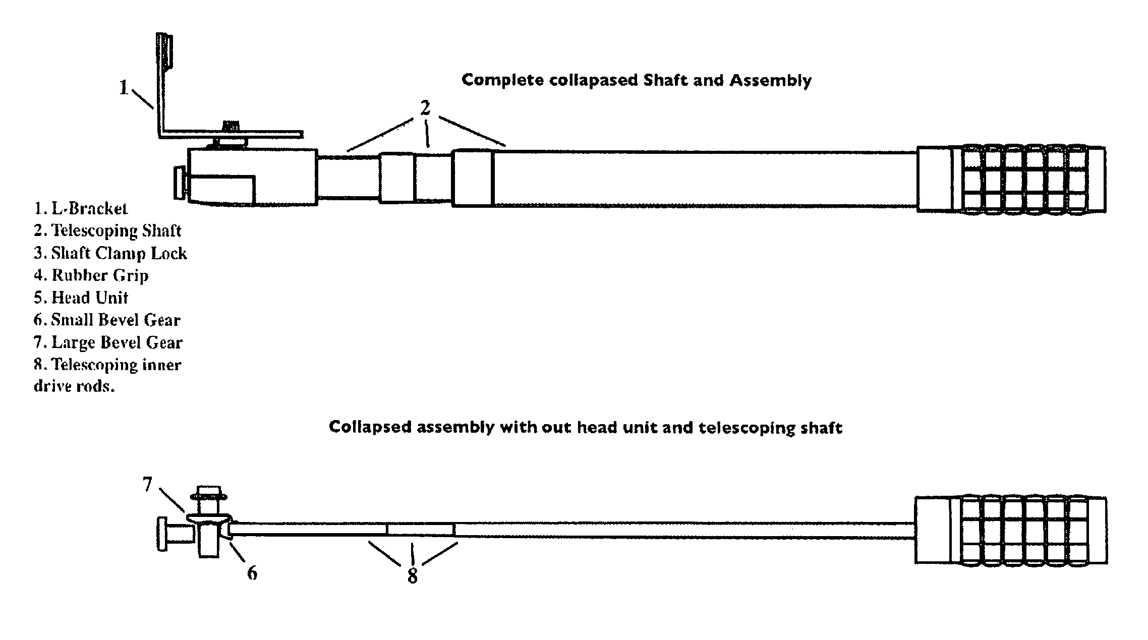
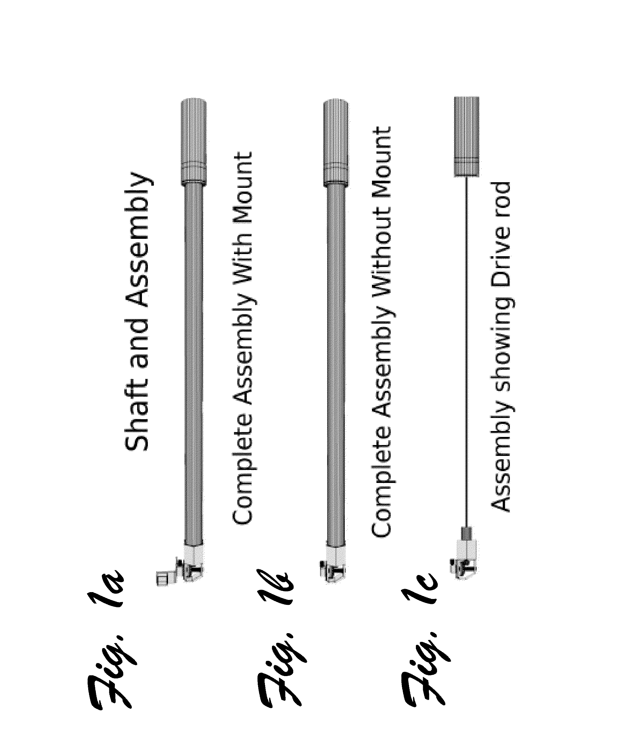
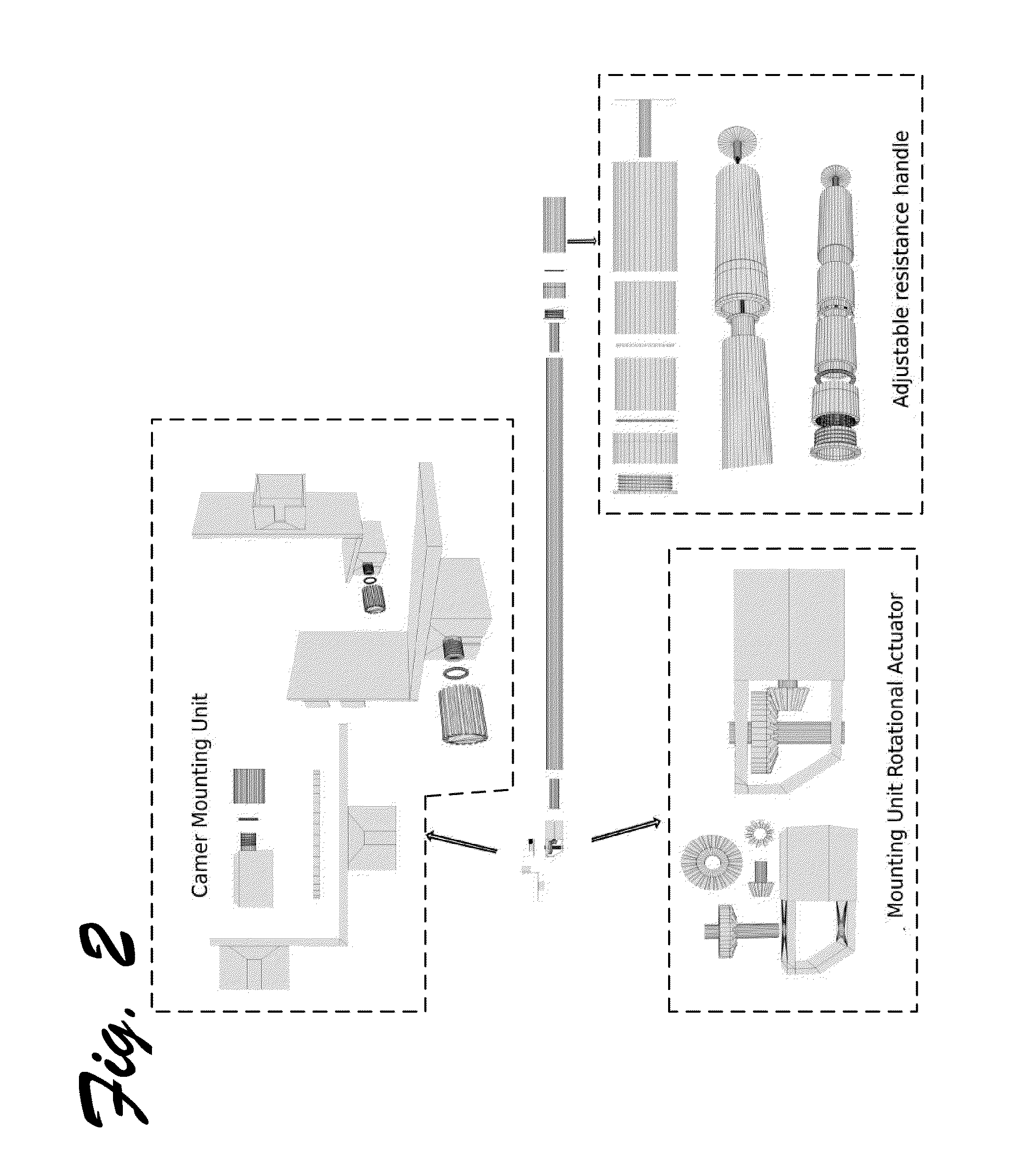
[0020]A long-distance pan or tilt device is disclosed as it may be implemented in an example embodiment as a media support system. The media support system may comprise a hollow shaft having a first shaft end and a second shaft end; a manually rotatable handle operatively mounted relative to the first shaft end; a mounting device rotational actuator operatively mounted to the second shaft end; a drive rod extending through the hollow shaft and operatively linking the rotatable handle with the mounting device rotational actuator; and a media mounting device mounted to the mounting device rotational actuator, the media mounting device being configured for carrying a media element, the media mounting device being operably connected with the mounting device rotational actuator in a manner to facilitate at least one of panning and tilting of the media element carried thereby.

[0021]It is noted that the media element may be a still camera or video camera, or any other media element (or oth...


PUM


Abstract

One embodiment of a portable media equipment support device comprising a hollow shaft having a first shaft end and a second shaft end. A manually rotatable handle is operatively mounted relative to the first shaft end and a mounting device rotational actuator is operatively mounted to the second shaft end. The manually rotatable handle is connected to mounting device rotational actuator by a drive rod internally running through said hollow shaft. A bevel gear system is internally located in said rotational actuator and used to translate motion approximately 90 degrees into a media mounting device. The media mounting device is used to secure and carry a media equipment element. The rotatable handle serves to control the motion of the drive rod and is thereby translated by the bevel gear system. This sequence of mechanical reactions is used to facilitate at least one of the panning or tilting motions of the media equipment. A locking screw connected to the head unit of the mounting device rotational actuator serves to secure the bevel gear system from rotation. Thereby allowing for said media equipment to be secured in a locked position, if desired. Other embodiments are described and shown.

Description

CROSS-REFERENCE TO RELATED APPLICATIONS[0001]This application claims the benefit of provisional patent application Ser. No. 61 / 757,338, filed 2013 Jan. 28 by Trenner Law.BACKGROUNDPrior Art[0002]The following is a tabulation of some prior art that presently appears relevant:[0003]Kind U.S. Pat. Pat. No.CodeIssue DatePatenteeU.S. 8,549,812B1Oct. 10, 2013Hong Fu Jin Precision industry(Shenzhen) co., Ltd.U.S. 327,730AOct. 6, 1885John B. SimsU.S. 20140014807A1Jan. 16, 2014Zeke L. KammBACKGROUND[0004]Photographers and videographers, among others (e.g., sound technicians) often need to position their equipment where the equipment cannot be readily held. While tripods are commercially available to steady camera equipment, these are typically used for stationary applications (e.g., holding a camera steady for taking a photograph of a sunset, or to avoid shaking Introduced by the user's hands when taking video). There many devices that are used to extend the scope of how said media equipment...

Claims


Application Information

Patent Timeline
IPC IPC(8): F16M13/00F16M13/04E04G3/00A47H1/10G03B17/00
CPCF16M13/04F16M13/00F16M11/08F16M11/2092F16M11/28G03B17/563
Inventor SWANSON, BENJAMIN ALEXANDER
Owner SWANSON BENJAMIN ALEXANDER
Why Eureka
Try Eureka