Linear LED illumination device with improved rotational hinge

a technology of rotational hinges and linear led lighting, which is applied in the direction of lighting support devices, lighting and heating apparatus, light source combinations, etc., can solve the problems of inevitably producing adjustment strain between adjacent fixtures, cumbersome and time-consuming, and complex design of rotational hinges used in linear led lighting fixtures

Active Publication Date: 2015-09-29
LUTRON TECH CO LLC
View PDF221 Cites 2 Cited by
  • Summary
  • Abstract
  • Description
  • Claims
  • Application Information

AI Technical Summary

Benefits of technology

[0013]Various embodiments are disclosed herein for providing an improved rotational hinge in an illumination device. The embodiments disclosed herein may be utilized together or separately, and a variety of features and variations can be implemented, as desired, to achieve optimum results. In addition, related systems and methods can be utilized with the embodiments disclosed herein to provide additional advantages or features.
[0015]Like some conventional lighting devices, the hinge mechanism described herein may allow the emitter housing to rotate approximately 180 degrees relative to the mounting bracket around a rotational axis of the hinge mechanism. Unlike conventional lighting devices, however, the rotational components of the disclosed hinge mechanism are positioned away from the rotational axis of the hinge mechanism, so that the power cable can be routed through the orifice of the power supply housing along the rotational axis of the hinge.
[0018]In some embodiments, the hinge element may further comprise a constant torque element that provides a substantially consistent amount of torque to the position holding gear, regardless of whether the position holding gear is stationary or in motion. In other embodiments, the hinge element may comprise a variable torque element that requires a larger amount of torque to move the position holding gear from a stationary position, and a smaller amount of torque once the position holding gear is in motion. Regardless, the hinge mechanism described herein enables the illumination device to be adjusted about the rotational axis and secured in a rotational position without the need for tools or an additional locking mechanism.

Problems solved by technology

However, this requirement complicates the design of the rotational hinges used in the linear lighting fixtures, as it prevents the hinges from both rotating and passing power through the same central axis.
However, this inevitably produces strain between adjacent fixtures that are adjusted to different angles.
This is both cumbersome and time consuming, and can be frustrating if the tools are misplaced.

Method used


Image

  • Linear LED illumination device with improved rotational hinge
  • Linear LED illumination device with improved rotational hinge
  • Linear LED illumination device with improved rotational hinge

Examples


Embodiment Construction

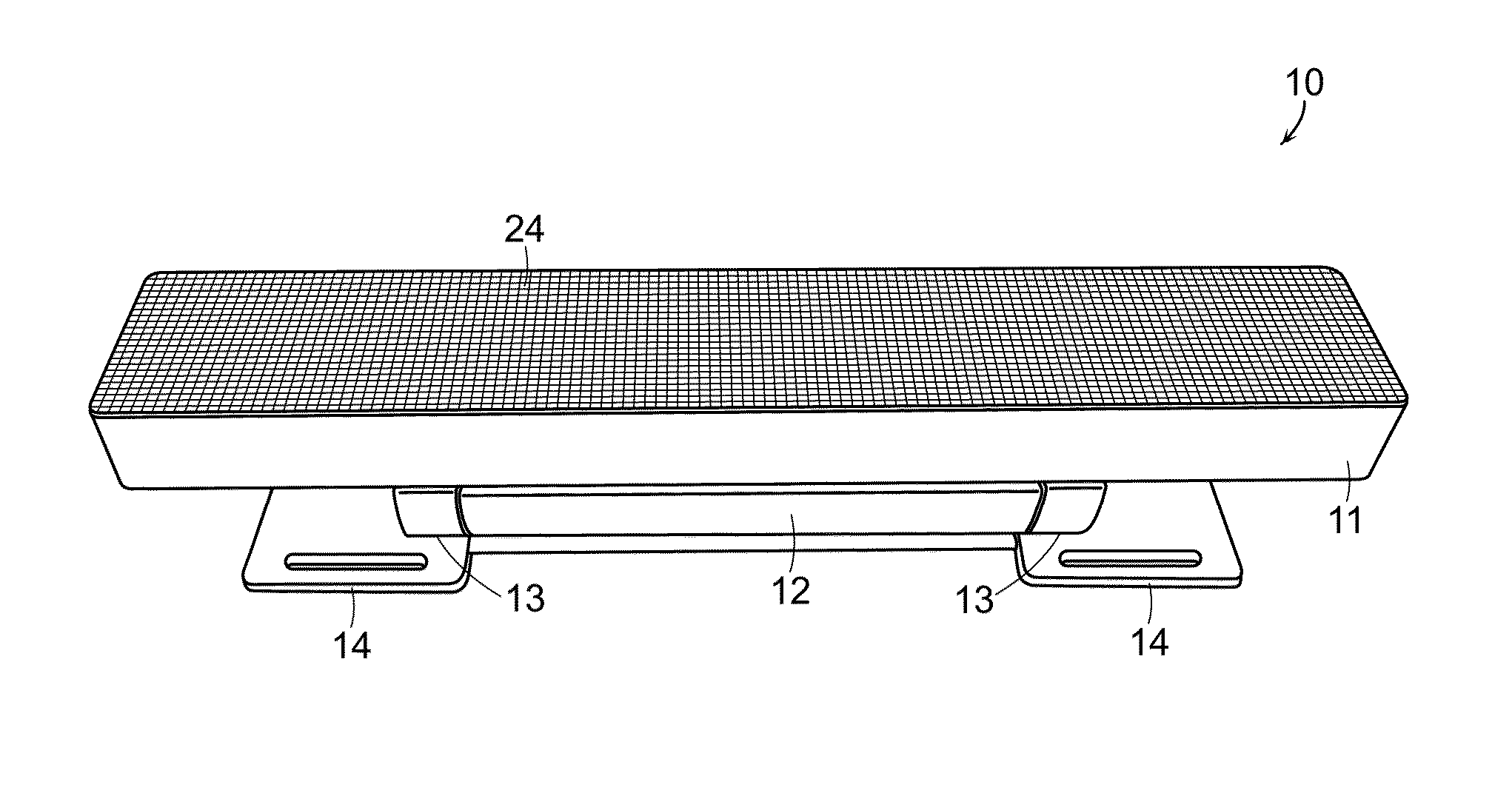
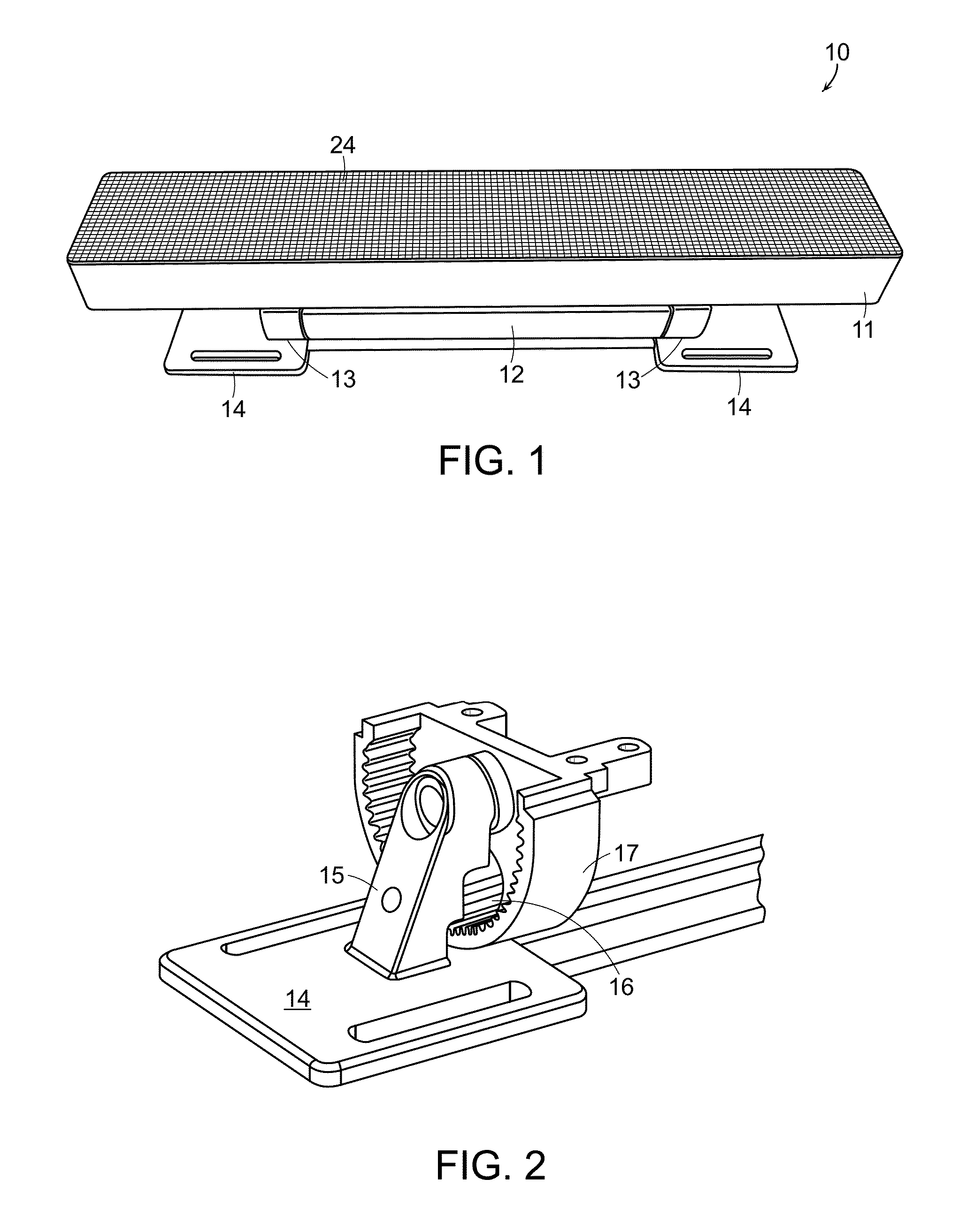
[0039]Turning now to the drawings, FIG. 1 is a picture of a linear LED lamp 10, according to one embodiment of the invention. As described in more detail below, linear LED lamp 10 produces light over a wide color gamut, thoroughly mixes the color components within the output beam, and uses an optical feedback system to maintain precise color over LED lifetime, and in some cases, with changes in temperature. The linear LED lamp 10 shown in FIG. 1 is powered by the AC mains, but may be powered by alternative power sources without departing from the scope of the invention. The light beam produced by LED lamp 10 can be symmetric or asymmetric, and can have a variety of beam angles including, but not limited to, 120×120, 60×60, and 60×30. If an asymmetric beam is desired, the asymmetric beam typically has a wider beam angle across the length of the lamp.

[0040]In general, LED lamp 10 comprises emitter housing 11, power supply housing 12, and rotating hinges 13. As shown more clearly in FI...


PUM


Abstract

A linear multi-color LED illumination device is described herein as including a rotational hinge, which allows a power cable of the illumination device to enter and exit through a rotational axis of the hinge, and which does not require special tools or an independent locking mechanism to secure in place.

Description

RELATED APPLICATIONS[0001]This application is related to the following co-pending applications: U.S. Patent application Ser. Nos. 14 / 097,339; 13 / 970,944; 13 / 970,964; 13 / 970,990; 12 / 803,805; and 12 / 806,118 now U.S Pat. No. 8,773,336; each of which is hereby incorporated by reference in its entirety.BACKGROUND[0002]1. Field of the Invention[0003]The invention relates to rotational hinge mechanisms for an illumination device, and more specifically, to a rotational hinge that allows a power cable of the illumination device to enter and exit through a rotational axis of the hinge. In addition, the rotational hinge described herein to allows the illumination device to be adjusted about the rotational axis and secured in a desired rotational position without the use of special tools or an additional locking mechanism.[0004]2. Description of Related Art[0005]Illumination devices using light emitting diodes (LEDs) provide many advantages over traditional light sources, such as fluorescent la...

Claims


Application Information

Patent Timeline
Patent Type & Authority Patents(United States)
IPC IPC(8): F21V21/30F21K99/00
CPCF21V21/30F21K9/30Y10S248/917F21V5/007F21V23/0457F21V27/02F21Y2103/10F21Y2105/10F21Y2105/12F21Y2113/13F21Y2115/10H05B45/22H05B45/3725
Inventor LOGAN, DEREK EDWARDMOLLNOW, TOMAS J.
Owner LUTRON TECH CO LLC
Why Eureka
Try Eureka