Leakage magnetic flux flaw inspection method and device

a magnetic flux and flaw technology, applied in measurement devices, instruments, computing, etc., can solve the problem of leakage magnetic flux generated on the surface, and achieve the effect of accurate identification, accurate identification of position and the size of the defect, and easy acquisition of optimal signal changes

Inactive Publication Date: 2015-09-29
UNIV OKAYAMA
View PDF12 Cites 0 Cited by
  • Summary
  • Abstract
  • Description
  • Claims
  • Application Information

AI Technical Summary

Benefits of technology

[0036]According to the present invention, a parallel component of a leakage magnetic flux is detected and thus a change of a magnetic field corresponding to a position of a defect can be obtained. Furthermore, a magnetic field signal of the leakage magnetic flux obtained by a sensor array is divided into two signals of a signal intensity and a phase orthogonal to each other, cosine or sine as a trigonometric function of a phase obtained by adding to a phase at each measurement point of a multipoint measurement at a plurality of positions, an adjustment phase to all the measurement points is obtained, an amount is obtained by multiplying the signal intensity and the trigonometric function, and thus a signal change optimum for detecting the defect can be obtained. Accordingly, a position and a size of the defect can be more accurately identified.
[0037]According to the present invention, through displaying the values of the product by the display unit, the optimum signal change can be easily obtained by changing the correction phase as desired. Thus, the position and the size of the defect can be identified more accurately.
[0038]According to the present invention, a parallel component of a leakage magnetic flux is detected and thus a change of a magnetic field corresponding to a position of a defect can be obtained. Furthermore, a magnetic field signal obtained by a sensor is divided into a signal intensity and a phase by a lock-in detector, cosine or sine as a trigonometric function of a phase obtained by adding to a phase at each measurement point of a multipoint measurement at a plurality of positions, an adjustment phase to all the measurement points is obtained, and an amount is obtained by multiplying the signal intensity and the trigonometric function, and thus an optimum signal change can be obtained. Accordingly, a position and a size of the defect can be more accurately identified.
[0039]According to the present invention, any correction phase can be input.
[0040]According to the present invention, a defect can be two-dimensionally detected.
[0041]According to the present invention, a plurality of sensors are arranged. Thus, the sensors needs not to be moved between magnetic pole portions during an inspection. Accordingly, the inspection can be performed at once without being affected by a change of a measurement condition.

Problems solved by technology

In the magnetic flux leakage inspection method using magnetism, when the steel product as the measured target is magnetized by the direct or alternating magnetization, if the measurement target has a defect on a surface, a leakage magnetic flux leakage is generated on the surface.

Method used


Image

  • Leakage magnetic flux flaw inspection method and device
  • Leakage magnetic flux flaw inspection method and device
  • Leakage magnetic flux flaw inspection method and device

Examples


first embodiment

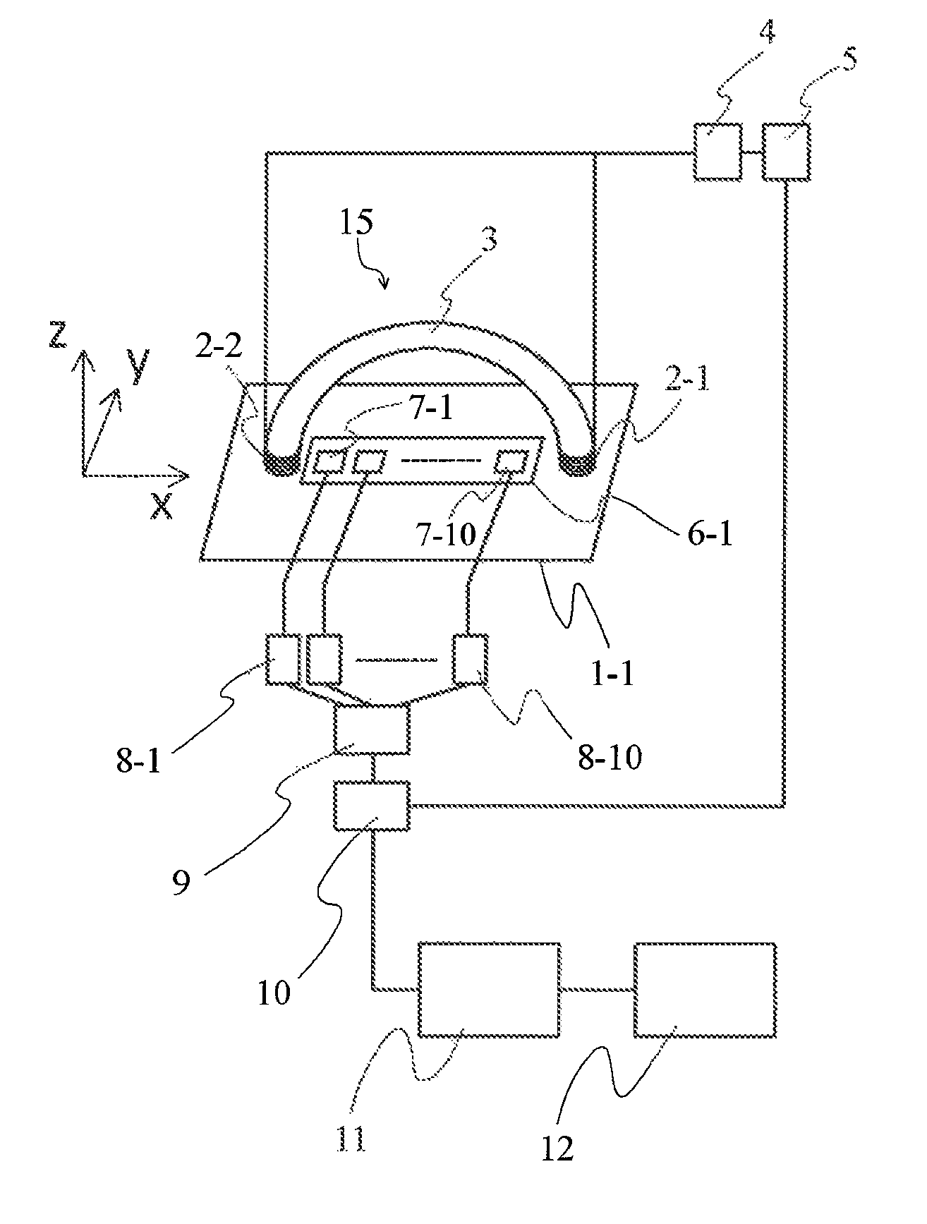
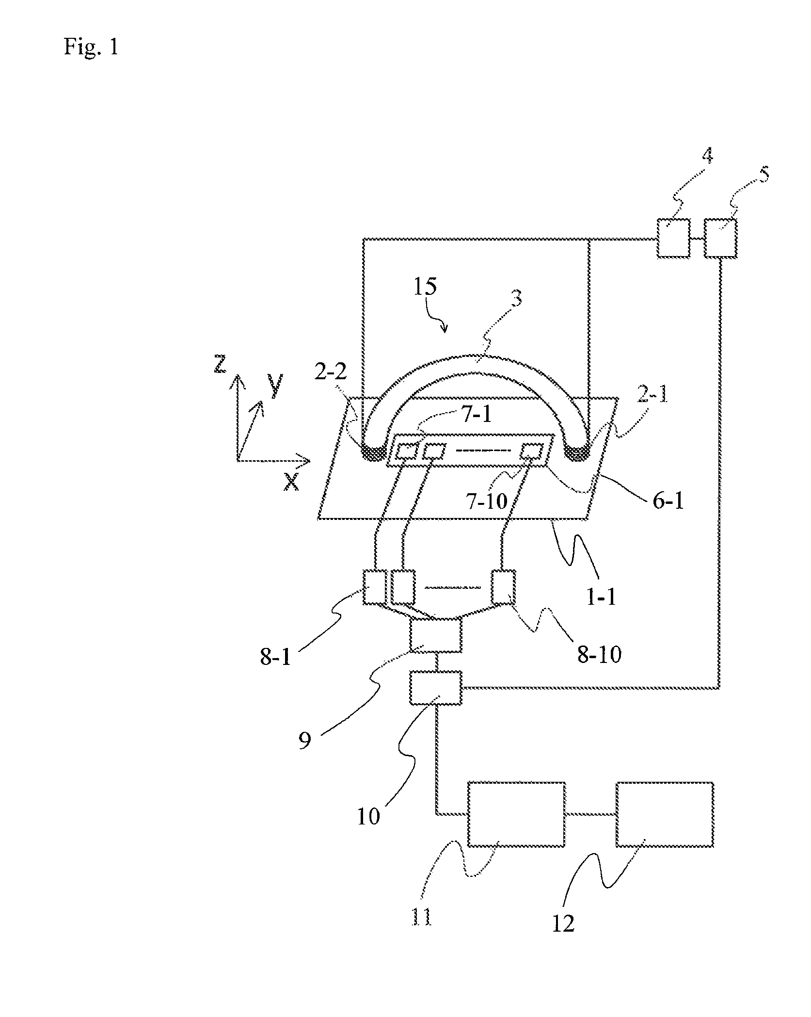
[0093]FIG. 1 is a schematic diagram showing a basic configuration of a magnetic flux leakage inspection apparatus employing a magnetic flux leakage inspection method as an embodiment of the present invention.

[0094]The magnetic flux leakage inspection apparatus is an apparatus that detects a leakage magnetic flux that leaks from an inspected object 1-1 to inspect a defect. As shown in FIG. 1, the magnetic flux leakage inspection apparatus mainly includes a magnetic field application unit 15, a magnetic sensor array 6-1, a lock-in detector 10, a signal analyzer 11, and a display mechanism 12.

[0095]The magnetic field application unit 15 is a magnetic field application unit that applies an alternating magnetic field to the inspected object 1-1 having a predetermined thickness and includes a pair of exciting coils 2-1 and 2-2, a yoke member 3, an exciting coil power source 4, and an oscillator 5. The exciting coils 2-1 and 2-2 are examples of magnetic pole portions and are respectively w...

second embodiment

[0120]Next, another embodiment of the magnetic flux leakage inspection apparatus employing the magnetic flux leakage inspection method according to the present invention is described with reference to FIG. 6.

[0121]The magnetic flux leakage inspection apparatus according to this embodiment is an apparatus that detects a leakage magnetic flux that leaks from an inspected object 1-2 to inspect a defect. As shown in FIG. 6, the magnetic flux leakage inspection apparatus mainly includes a magnetic field application unit 25, a magnetic sensor array 6-2, as well as the lock-in detector 10, the signal analyzer 11, and the display mechanism 12 shown in FIG. 1. The magnetic sensor array 6-2, the lock-in detector 10, the signal analyzer 11, and the display mechanism 12 are same as those in the first embodiment and detail description thereof will be omitted.

[0122]The magnetic field application unit 25 is a magnetic field application unit that applies an alternating magnetic field to the cylindr...

third embodiment

[0127]Next, still another embodiment of the magnetic flux leakage inspection apparatus employing the magnetic flux leakage inspection method according to the present invention is described by referring to FIG. 7.

[0128]FIG. 7 shows another mode for providing the same function of the embodiment in FIG. 6 of the present invention. In FIG. 6, to measure the cylindrical steel pipe, the exciting coils 2-3 and 2-4 are wound around the cylinders. However, if the steel pipe has a large diameter, the exciting coil may be difficult to wound. As a method to address this, an exciting coil that applies a magnetic field to an inspected object 1-3 can be formed by combining multiple rectangular exciting coils 13 each having a predetermined size to wrap around the inspected objected 1-3 (steel pipe) as shown in FIG. 7. Specifically, each of the rectangular exciting coils 13 is formed on a flexible exciting coil base member 14 and thus can snugly fit to the cylindrical shape and can be adhered on a s...


PUM

PropertyMeasurementUnit
sizeaaaaaaaaaa
thicknessaaaaaaaaaa
depthaaaaaaaaaa

Abstract

A magnetic flux leakage inspection method generates a magnetic flux parallel to a surface of an inspected object, and detects a magnetic flux that leaks from the surface of the inspected object with a magnetic sensor. The method includes exciting coils that generate an alternating magnetic field having a variable frequency, an exciting coil power source, a magnetic sensor, a lock-in detector, and a signal analyzer that analyzes changes of a signal intensity and a phase of the output of the magnetic sensor with output signals of the lock-in detector. The method obtains cosine or sine as a trigonometric function of a phase obtained by adding to the phase at each measurement point of multipoint measurement, an adjustment phase common to all the measurement points, and displays an analytical value obtained by multiplying the signal intensity and the sine or cosine at each measurement point with any adjustment phase.

Description

TECHNICAL FIELD[0001]The present invention relates to a method and an apparatus for inspecting a defect of an inspected objected by applying an alternating magnetic field to the inspected object and detecting a leakage magnetic flux that leaks from a surface of the inspected object.BACKGROUND ART[0002]A magnetic flux leakage inspection method using magnetism is one of methods that have been used for inspecting a defect of a steel material. The magnetic flux leakage inspection method magnetizes a measured target by direct or alternating magnetization and detects a magnetic flux that leaks from a surface of the measured target mainly using a search coil as a magnetic sensor. Recently, a magnetic resistor device (MR), a hall device, a magnetic impedance device (MI), and the like have begun to be used as the magnetic sensor. In the magnetic flux leakage inspection method using magnetism, when the steel product as the measured target is magnetized by the direct or alternating magnetizati...

Claims


Application Information

Patent Timeline
Patent Type & Authority Patents(United States)
IPC IPC(8): G01R35/00G01N27/83
CPCG01N27/83
Inventor TSUKADA, KEIJI
Owner UNIV OKAYAMA
Why Eureka
Try Eureka