Passive touch pen

Inactive Publication Date: 2015-09-29
PRIMAX ELECTRONICS LTD
View PDF12 Cites 4 Cited by
  • Summary
  • Abstract
  • Description
  • Claims
  • Application Information

AI Technical Summary

Benefits of technology

This patent is about a new type of touch pen that has a venting system to make it cheaper and easier to make. Its design is simpler and more efficient than traditional touch pens.

Problems solved by technology

However, the conventional passive touch pen 1 still has some drawbacks.
For example, the use of the rubber tip supporting member 15 may increase the fabricating cost and the structural complexity of the passive touch pen 1.
Therefore, it is an important issue to provide an improved passive touch pen without the rubber tip supporting member 15.

Method used


Image

  • Passive touch pen
  • Passive touch pen
  • Passive touch pen

Examples


Embodiment Construction

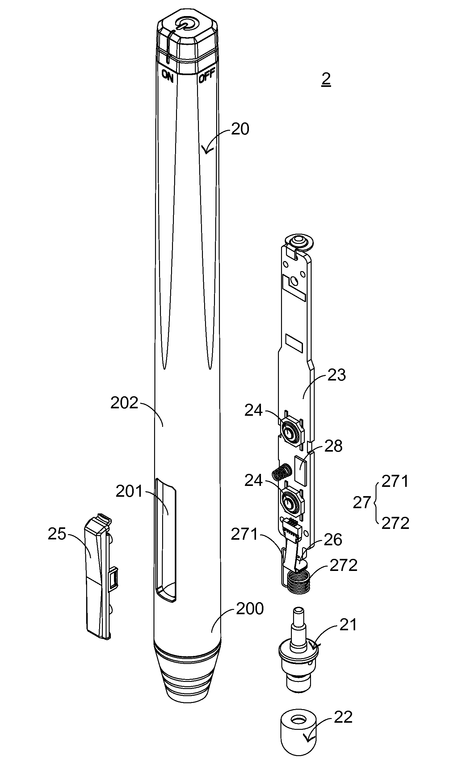
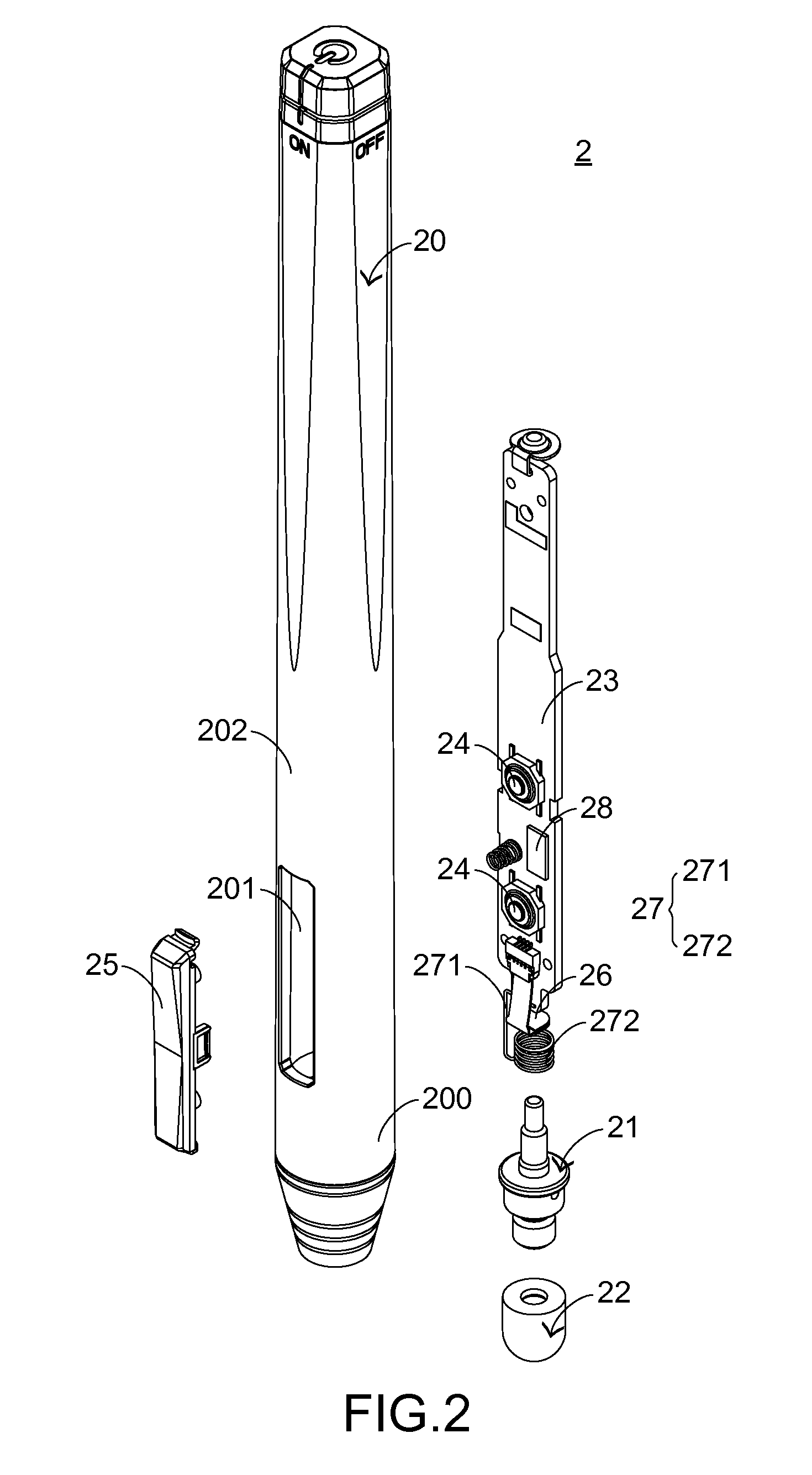
[0022]Hereinafter, a passive touch pen 2 according to a first embodiment of the present invention will be illustrated with reference to FIGS. 2˜5. FIG. 2 is a schematic exploded view illustrating a passive touch pen according to a first embodiment of the present invention. FIG. 3 is a schematic exploded view illustrating a fixing post and a conductive rubber tip of the passive touch pen of FIG. 2. FIG. 4 is a schematic cutaway view illustrating the fixing post and the conductive rubber tip of the passive touch pen of FIG. 3. FIG. 5 is a schematic cutaway view illustrating the passive touch pen according to the first embodiment of the present invention.

[0023]The components of the passive touch pen 2 and the assembling sequence thereof will be illustrated as follows. As shown in FIG. 2, the passive touch pen 2 comprises a pen tube 20, a fixing post 21, a conductive rubber tip 22, a circuit board 23, two switch elements 24, a plastic pressing element 25, a pressure sensor 26, a conduct...


PUM


Abstract

A passive touch pen for a capacitive touch screen is provided. The passive touch pen includes a pen tube, a fixing post, and a conductive rubber tip. The pen tube has a vent. The fixing post is disposed within the pen tube, and includes a first perforation and a second perforation. The first perforation is open to a top surface of the fixing post. The second perforation is open to a lateral surface of the fixing post. The conductive rubber tip is sheathed around the fixing post and exposed outside the pen tube. After the conductive rubber tip is no longer compressed, air can be quickly introduced into to a vacant space between the conductive rubber tip and the top surface of the fixing post through the vent, the second perforation and the first perforation. Consequently, the conductive rubber tip is restored to an original non-compressed shape.

Description

FIELD OF THE INVENTION[0001]The present invention relates to a touch pen, and more particularly to a passive touch pen for a capacitive touch screen.BACKGROUND OF THE INVENTION[0002]Nowadays, the commercially available touch screens are classified into several types, including a resistive touch screen, an acoustic wave touch screen, an infrared touch screen and a capacitive touch screen. When an external force is exerted on the resistive touch screen, a voltage is generated and a command is recognized according to the voltage. Moreover, acoustic waves or infrared rays pass over the surface of the acoustic wave touch screen or the infrared touch screen. By touching the surface of the acoustic wave touch screen or the infrared touch screen, the travelling path of the acoustic wave or the infrared ray is blocked and thus the corresponding command is recognized. When the human body is contacted with the capacitive touch screen, the capacitance value of the touch point of the capacitive ...

Claims


Application Information

Patent Timeline
IPC IPC(8): G06F3/044G06F3/033G06F3/0354G06F3/03
CPCG06F3/044G06F3/03545G06F3/033G06F3/03G06F3/0393
Inventor CHANG, A-MINGTSENG, YING-CHE
Owner PRIMAX ELECTRONICS LTD
Why Eureka
Try Eureka