Electrophoretic display capable of reducing passive matrix coupling effect

a technology of electrophoretic display and coupling effect, which is applied in the direction of non-linear optics, static indicating devices, instruments, etc., can solve the problems of poor driving method of prior art for the passive matrix panel, and achieve the effects of reducing the coupling effect of passive matrix

Active Publication Date: 2015-09-29
YUANHAN MATERIALS INC
View PDF5 Cites 40 Cited by
  • Summary
  • Abstract
  • Description
  • Claims
  • Application Information

AI Technical Summary

Benefits of technology

[0006]An embodiment provides an electrophoretic display capable of reducing passive matrix coupling effect. The electrophoretic display includes an electrophoretic panel, a coupling capacitor group, a plurality of first scan lines, and a plurality of second scan lines. The electrophoretic panel includes a plurality of pixels, and has a first axis direction. The coupling capacitor group is installed on the first axis direction, where the coupling capacitor group includes a plurality of coupling capacitors. The plurality of first scan lines is installed on the first axis direction. The plurality of second scan lines is installed on a second axis direction of the electrophoretic panel, where the first axis direction is perpendicular to the second axis direction. Each pixel of the plurality of pixels is coupled to a storage capacitor and corresponds to a coupling capacitor, the storage capacitor is coupled to a first scan line of the plurality of first scan lines and a second scan line of the plurality of second scan lines, the coupling capacitor is coupled to another first scan line and the second scan line, and the coupling capacitor is not coupled to any pixel.
[0007]Another embodiment provides an electrophoretic display capable of reducing passive matrix coupling effect. The electrophoretic display includes an electrophoretic panel, a coupling capacitor group, a plurality of first scan lines, and a plurality of second scan lines. The electrophoretic panel includes a plurality of pixels, and has a first axis direction. The coupling capacitor group is installed on the first axis direction, where the coupling capacitor group includes a plurality of coupling capacitors. The plurality of first scan lines is installed on the first axis direction. The plurality of second scan lines is installed on a second axis direction of the electrophoretic panel, where the first axis direction is perpendicular to the second axis direction. Each pixel of the plurality of pixels is coupled to a storage capacitor and corresponds to a coupling capacitor of the plurality of coupling capacitors, the storage capacitor is coupled to a first scan line of the plurality of first scan lines and a second scan line of the plurality of second scan lines, the coupling capacitor is composed of a parallel storage capacitor group of the plurality of pixels, and the parallel storage capacitor group is located at a non-active region of the electrophoretic panel.
[0008]The present invention provides an electrophoretic display capable of reducing passive matrix coupling effect. The electrophoretic display utilizes a plurality of coupling capacitors of a coupling capacitor group to reduce coupling voltages coupled to a plurality of pixels corresponding to a pixel when the pixel is driven according to a driving voltage. Thus, compared to the prior art, the present invention can ensure that each pixel of the electrophoretic panel displays a color wanted by a user.

Problems solved by technology

Therefore, the prior art is not a good driving method for the passive matrix panel 100.

Method used


Image

  • Electrophoretic display capable of reducing passive matrix coupling effect
  • Electrophoretic display capable of reducing passive matrix coupling effect
  • Electrophoretic display capable of reducing passive matrix coupling effect

Examples


Embodiment Construction

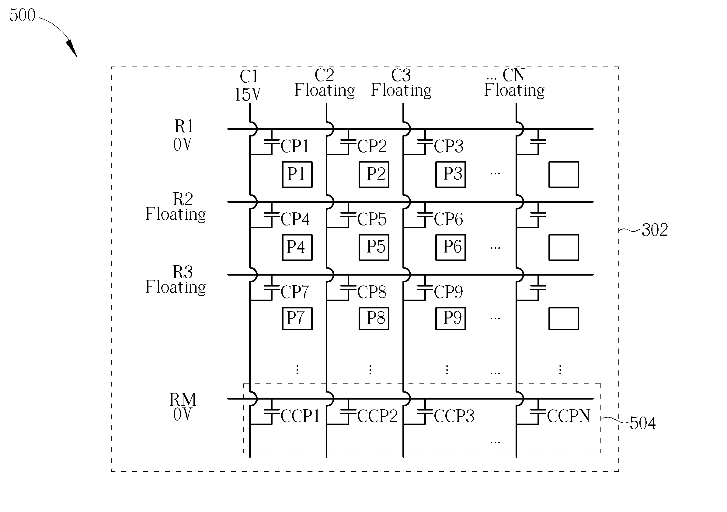
[0020]Please refer to FIG. 3. FIG. 3 is a diagram illustrating an electrophoretic display 300 capable of reducing passive matrix coupling effect according to an embodiment. The electrophoretic display 300 includes an electrophoretic panel (passive matrix panel) 302, a coupling capacitor group 304, a plurality of first scan lines C1-CN, and a plurality of second scan lines R1-RM, where the plurality of first scan lines C1-CN are installed on a vertical axis direction of the electrophoretic panel 302, the plurality of second scan lines R1-RM are installed on a horizontal axis direction of the electrophoretic panel 302, and N, M are positive integers. The electrophoretic panel 302 includes a plurality of pixels. The coupling capacitor group 304 is installed on the vertical axis direction, where the coupling capacitor group 304 includes a plurality of coupling capacitors CCP1-CCPM, where capacitances of the plurality of coupling capacitors CCP1-CCPM are the same or different. In additio...


PUM

PropertyMeasurementUnit
driving voltageaaaaaaaaaa

Abstract

An electrophoretic display capable of reducing passive matrix coupling effect includes an electrophoretic panel, a coupling capacitor group, a plurality of first scan lines, and a plurality of second scan lines. The electrophoretic panel includes a plurality of pixels. The coupling capacitor group includes a plurality of coupling capacitors. Each pixel of the plurality of pixels is coupled to a storage capacitor and corresponds to a coupling capacitor, the storage capacitor is coupled to a first scan line and a second scan line, the coupling capacitor is coupled to another first scan line and the second scan line, and the coupling capacitor is not coupled to any pixel.

Description

BACKGROUND OF THE INVENTION[0001]1. Field of the Invention[0002]The present invention relates to an electrophoretic display, and particularly to an electrophoretic display that can utilize a coupling capacitor group to reduce passive matrix coupling effect.[0003]2. Description of the Prior Art[0004]Please refer to FIG. 1 and FIG. 2. FIG. 1 is a diagram illustrating a pixel P1 of a passive matrix panel 100 being driven according to the prior art, and FIG. 2 is a diagram illustrating an equivalent circuit of storage capacitors CP2-CP9 corresponding to pixels P2-P9 adjacent to the pixel P1 when the pixel P1 is driven, where the pixel P1 is coupled to a first scan line 102 and a second scan line 104. As shown in FIG. 1, when the pixel P1 is driven, the first scan line 102 is applied to a first driving voltage (e.g. 15V), the second scan line 104 is applied to a second driving voltage (e.g. 0V), and other first scan lines and other second scan lines of the passive matrix panel 100 are fl...

Claims


Application Information

Patent Timeline
Patent Type & Authority Patents(United States)
IPC IPC(8): G09G3/34G02F1/167
CPCG09G3/3446G02F1/167G09G3/344G09G2300/06G09G2320/0209
Inventor WU, YAN-LIANGHUNG, CHI-MAOSUN, WEI-MINTIEN, PEI-LINHSU, CHIH-YUANCHENG, HSIAO-LUNG
Owner YUANHAN MATERIALS INC
Why Eureka
Try Eureka