Device and system for controlling the movement of a furniture part, mounting fixture for said device and piece of furniture

Active Publication Date: 2015-10-06
GRASS GMBH
View PDF13 Cites 0 Cited by
  • Summary
  • Abstract
  • Description
  • Claims
  • Application Information

AI Technical Summary

Benefits of technology

[0004]The object of the invention is to provide a device or fixture of the above-mentioned type or a corresponding system and a piece of furniture which is accordingly equipped, wherein requirements with regard to financial and technical considerations can be fulfilled more effectively compared to previous solutions.
[0005]The invention starts in the first place from a mounting fixture for attaching a device for controlling the movement of a furniture part which is received on a stationary furniture part so as to be movable in a driven manner. One aspect consists in the fact that a fastening mechanism is provided, with elongate profiles which extend separately from each other with a clearance in between them and to which the device for controlling the movement can be attached. Various advantages in a financial or technical regard may be achieved in this way. Firstly, the mounting fixture can be purposefully adapted to allow stable and flexibly employable attachment of the device. Furthermore, the mounting fixture itself can be configured on a piece of furniture in an extremely compact manner, even the accommodation of the device for controlling the movement on the mounting fixture requiring just comparatively very little additional overall space. Compact packaging for transportation prior to fitting into the piece of furniture is also possible. Overall, according to the invention, the useful space provided with a piece of furniture is reduced only insignificantly by the mounting fixture or by the device attached thereto for controlling the movement. In addition, with elongate profiles which can be formed with low weight or require little material to be used, dimensions present in the piece of furniture or a furniture part can be overcome in all cases; this is often helpful for reasons of stable fastening. This allows the mounting fixture itself to be attached with comparatively few difficulties or if appropriate to different attachment points in various types of furniture.
[0006]An important advantage may also be identified in the fact that the mounting fixture, with the profiles extending separately from each other with a clearance in between them, combines maximum usability with minimum complexity. The term “clearance” may be understood, in accordance with a clear width, for example as the free space between uprights of a bridge or opposing door frames. A clearance is formed by a free space between the profiles, in particular while providing a material-free intermediate region of the profiles. The clearance is present in particular over relevant dimensions along the profiles, if appropriate over their entire or almost entire length. The clearance can be used to form, in particular, a free passage, extending up to the profiles themselves, transversely to the longitudinal extension of the profiles. The clearance or the material-free region between the profiles can also be singly or multiply interrupted over the length of the profiles, in particular via a small number of interruptions, which are narrow relative to the length of the profiles, of the clearance.

Problems solved by technology

Furthermore, the mounting fixture itself can be configured on a piece of furniture in an extremely compact manner, even the accommodation of the device for controlling the movement on the mounting fixture requiring just comparatively very little additional overall space.

Method used


Image

  • Device and system for controlling the movement of a furniture part, mounting fixture for said device and piece of furniture
  • Device and system for controlling the movement of a furniture part, mounting fixture for said device and piece of furniture
  • Device and system for controlling the movement of a furniture part, mounting fixture for said device and piece of furniture

Examples


Embodiment Construction

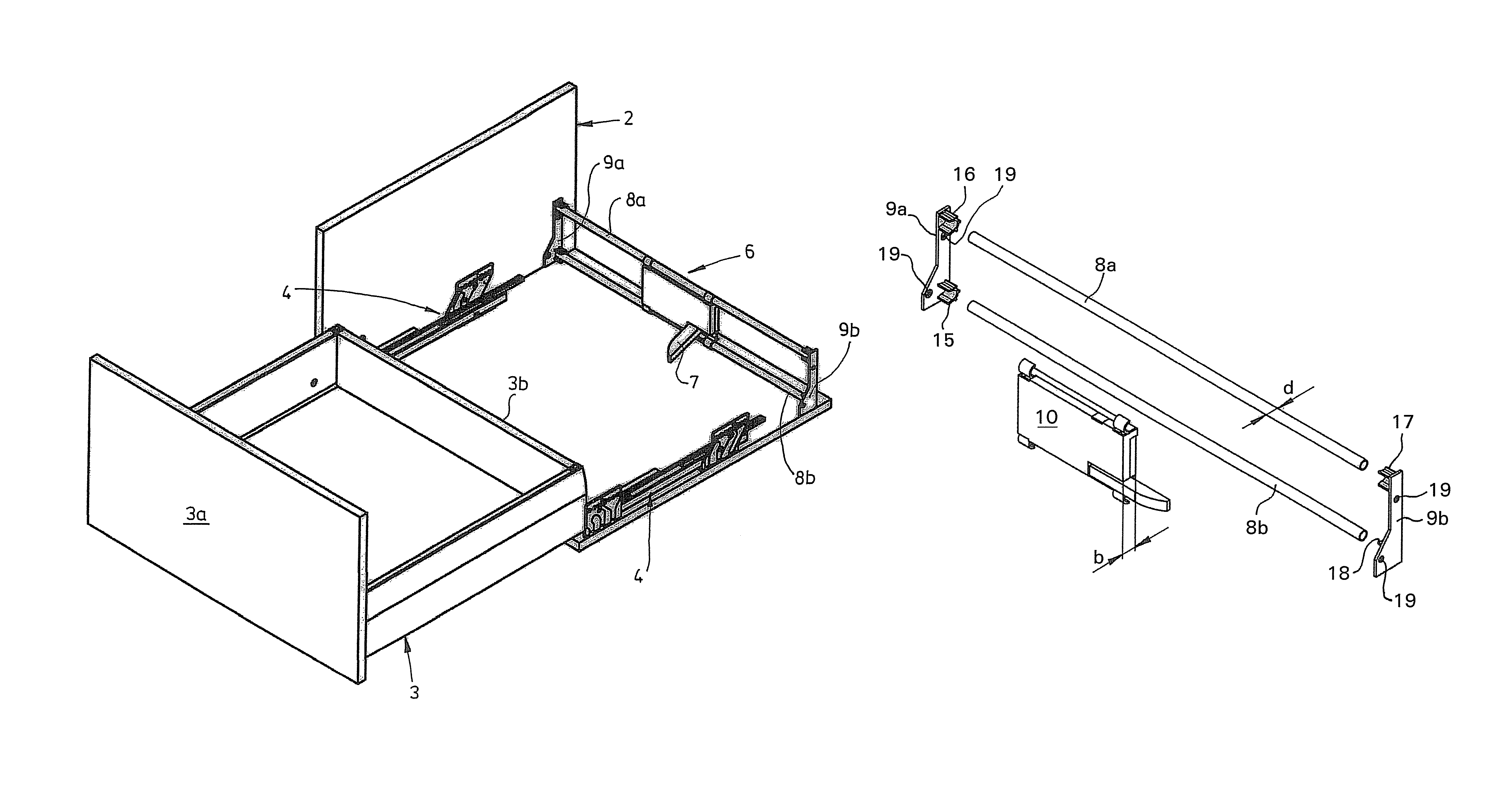
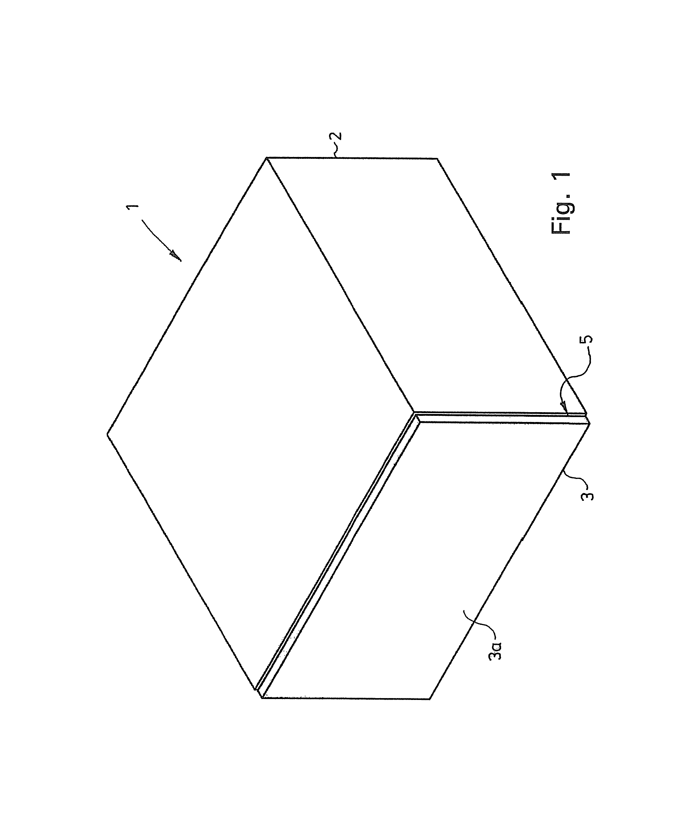
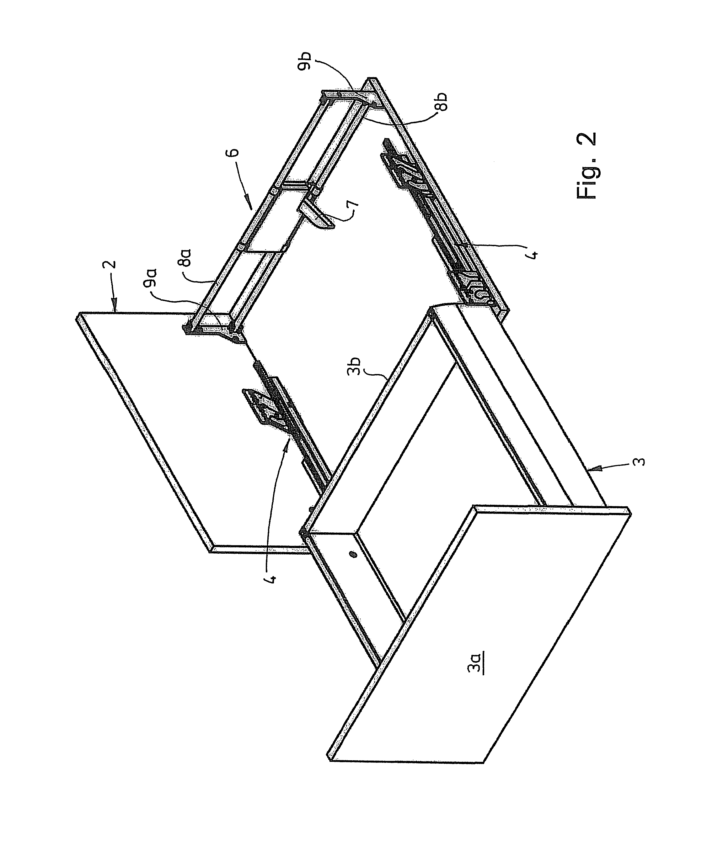
[0034]FIGS. 1 and 2 show a piece of furniture 1 with a body 2 and a drawer 3 which is displaceable in the body 2 via a pull-out guide 4. The pull-out guide 4 comprises in particular a full extension which is known per se and has a drawer-side drawer rail, a body-side fixed rail and a central rail which is received so as to be movable therebetween. In FIG. 1, the drawer 3 is in a closing position in which a front gap 5 of, for example, a few millimeters is formed between the body 2 and an inside of a front part 3a of the drawer 3. The front part 3a does not have a handle in the example shown, although a handle may be present.

[0035]The front gap serves primarily to allow, by pressing on the front part 3a for an ejecting process, a triggering command in which the drawer 3 can be moved in the direction toward the body 2 over a few millimeters while reducing the front gap 5. A triggered ejecting process is carried out using an ejection device 6 according to the invention. If, in the stat...


PUM


Abstract

A mounting fixture for attaching at least one device for controlling the movement of a furniture part which is received on a stationary furniture part so as to be movable in a driven manner. According to the invention, a fastening mechanism is provided, with elongate profiles which extend separately from each other with a clearance in between them and to which the device for controlling the movement can be attached.

Description

CROSS REFERENCE TO RELATED APPLICATIONS[0001]This application is a continuation of International Application No. PCT / EP2008 / 003512 filed Apr. 30, 2008, which designated the United States, and claims the benefit under 35 USC §119(a)-(d) of German Application No. 20 2007 006 300.8 filed Apr. 30, 2007, the entireties of which are incorporated herein by reference.FIELD OF THE INVENTION[0002]The invention relates to a mounting fixture, a device, a system and a piece of furniture.BACKGROUND OF THE INVENTION[0003]Arrangements for mounting or for attaching a device for controlling the movement of a furniture part are known in the furniture sector. In modern pieces of furniture, in addition to aesthetic aspects, ease of use of the pieces of furniture is becoming increasingly important. For this purpose, use may be made, for controlling the movement of a furniture part, of a broad range of devices, for example devices which assist in a driven manner opening or closing or which dampen the move...

Claims


Application Information

Patent Timeline
Patent Type & Authority Patents(United States)
IPC IPC(8): A47B88/04
CPCA47B88/0477A47B88/463
Inventor SCHNEIDER, KLAUS
Owner GRASS GMBH
Why Eureka
Try Eureka