
Impact hex thread protectors

a technology of protectors and threads, applied in the direction of hose connections, pipe protection against damage/wear, packaging, etc., can solve the problems of reducing the service life of the socket, increasing the difficulty of aligning the socket onto the hex head, etc., and achieves the effect of avoiding repetitive injury, reusable installation, and easy removal

Active Publication Date: 2015-10-06
YODER MICHAEL E
View PDF12 Cites 6 Cited by
  • Summary
  • Abstract
  • Description
  • Claims
  • Application Information

AI Technical Summary

Benefits of technology

This patent is about improving thread protectpers for pins and bocks. The new protecters are durable, reusable, and can be installed with a constant torque without risking injury. Additionally, they can be easily removed under cold conditions with commercially available tools. The main benefit is the increased safety and efficiency of the protecters.

Problems solved by technology

If the size of the hex head is greater than about 80 percent, a socket lacks a sufficient base and it becomes more difficult to align the socket onto the hex head.

Method used


Image

  • Impact hex thread protectors
  • Impact hex thread protectors
  • Impact hex thread protectors

Examples


second embodiment

4. Second Embodiment

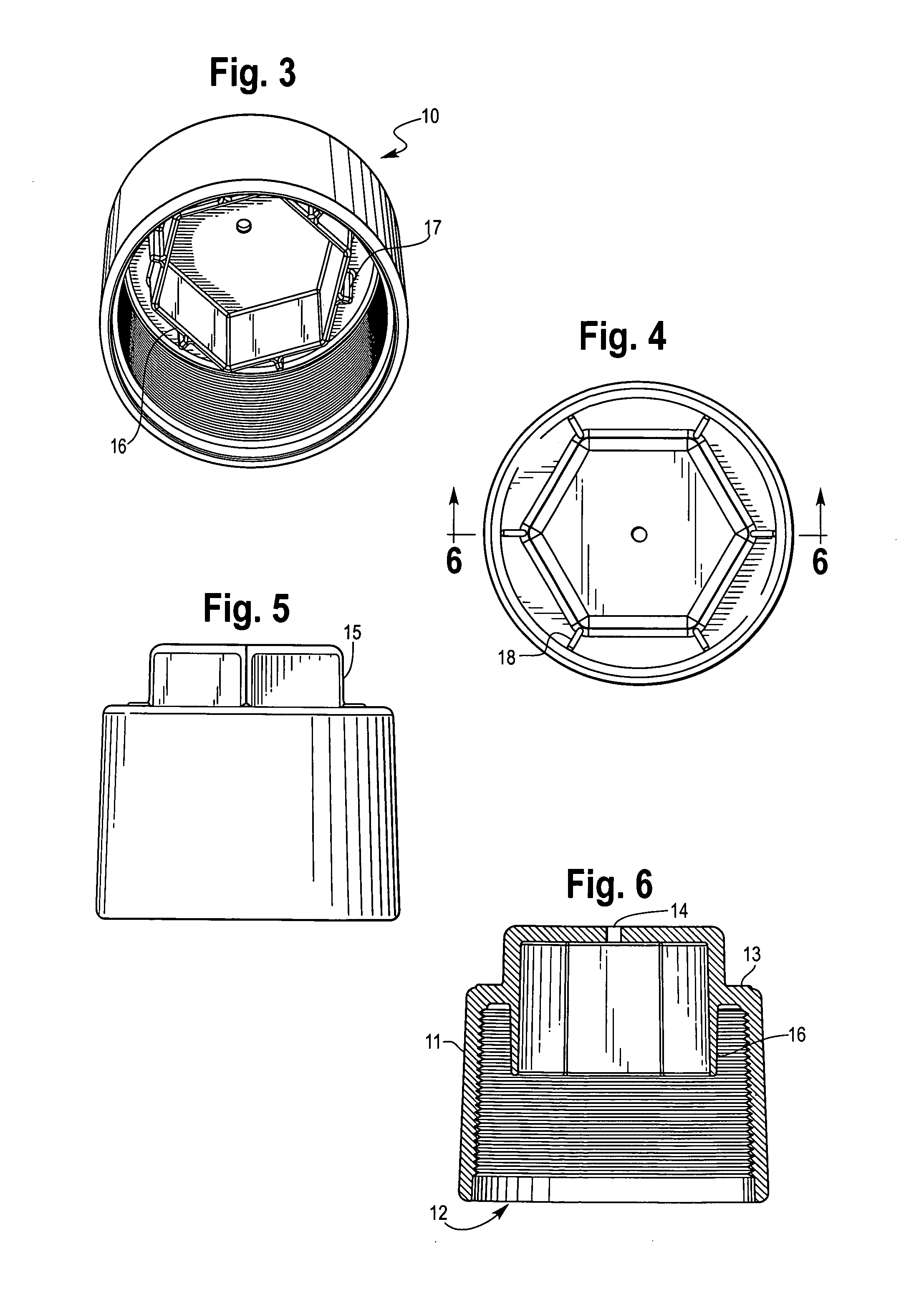
[0050]A second embodiment of the pin end thread protector 110 is shown in FIGS. 11 to 14 and a second embodiment of the box end thread protector 120 is shown in FIGS. 15 to 18. The second embodiments are similar to the first embodiments except the closed ends 113 and 123 and the hex heads 115 and 125 are recessed. While the hex heads of this embodiment project outwardly from the closed ends, the topes of the hex heads do not extend past the tops of the cylinders. The recessed position of the hex heads minimizes the risk of damage during shipment from the point of manufacture to the point of use of the pipe section-coupling. There is sufficient space between the outside of the hex heads and the surrounding wall to accommodate a socket of the type shown in FIG. 27.

third embodiment

5. Third Embodiment

[0051]A third embodiment of the pin end thread protector 210 is shown in FIGS. 19 to 22 and a second embodiment of the box end thread protector 220 is shown in FIGS. 23 to 26. The third embodiments are similar to the first embodiments except there are deep recesses 218 and 228 and in the interiors of the hex heads. The recesses accommodate cylindrical prongs that are commonly used to move the pipe section—coupling assemblies at the manufacturing or distribution site and at the rig or construction site.

6. Use

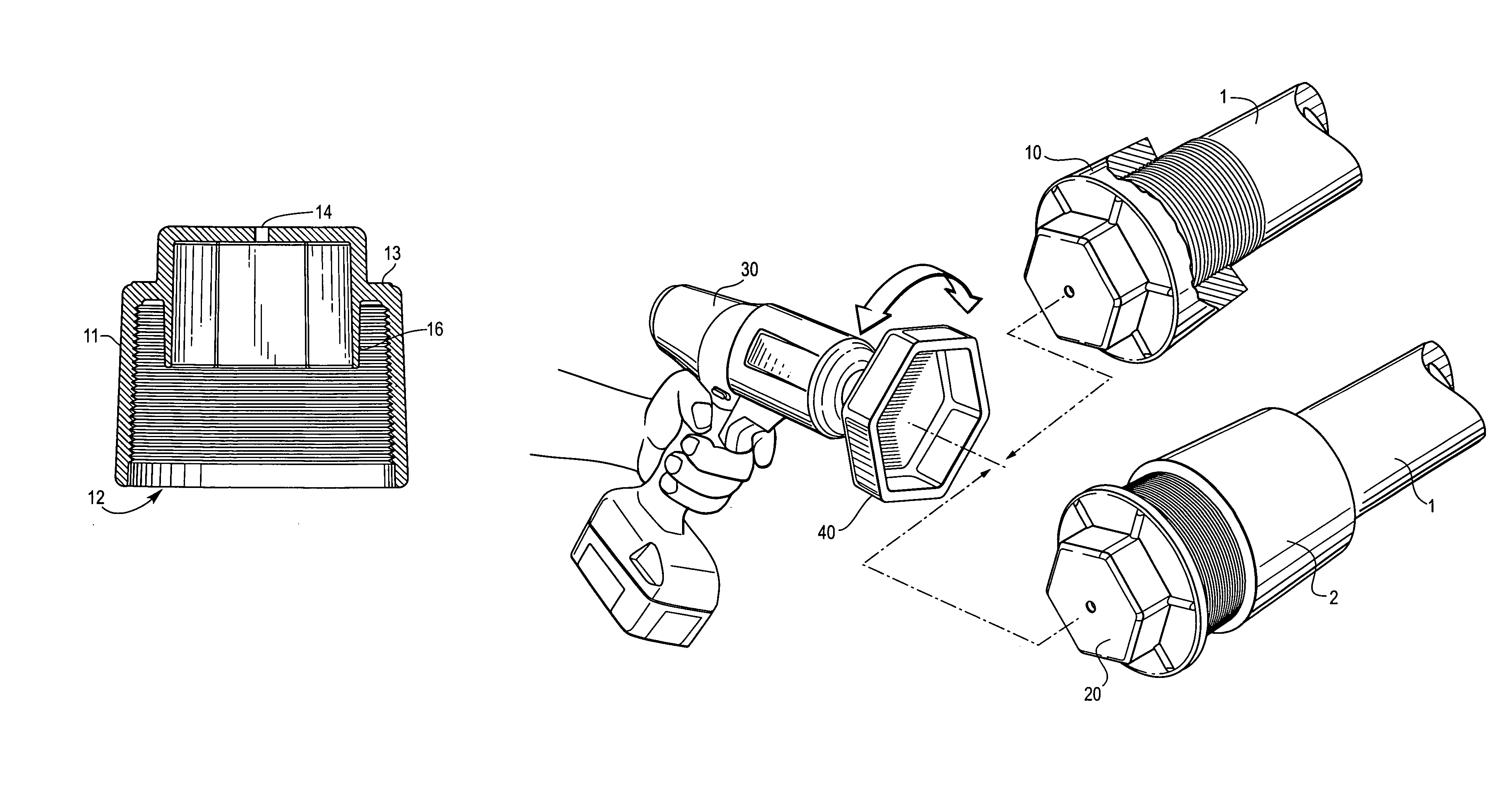
[0052]The thread protectors are generally installed on pipe section-coupling assemblies at the point of manufacture or distribution. The protectors are preferably installed using an impact wrench or the like fitted with a socket of the appropriate size. Referring now to FIG. 27, an impact wrench 30 with a socket 40 is advantageously used to install and remove both the pin end thread protector and the box end thread protector. Impact wrenches and sockets are wid...


PUM

PropertyMeasurementUnit
Fractionaaaaaaaaaa
Diameteraaaaaaaaaa
Sizeaaaaaaaaaa

Abstract

A thread protection assembly protects the exposed threads on the pin end and the box end of a section of pipe attached to a coupling. The assembly contains a pin end thread protector and a box end thread protector. The pin end thread protector has a cylindrical sleeve with internal threads adapted to mate with exposed external threads on the pin end of the pipe, an open end, and a closed end having an outwardly projecting hex head. The box end thread protector has a cylinder with external threads adapted to mate with the exposed internal threads on the box end of the coupling and a closed end having an outwardly projecting hex head.

Description

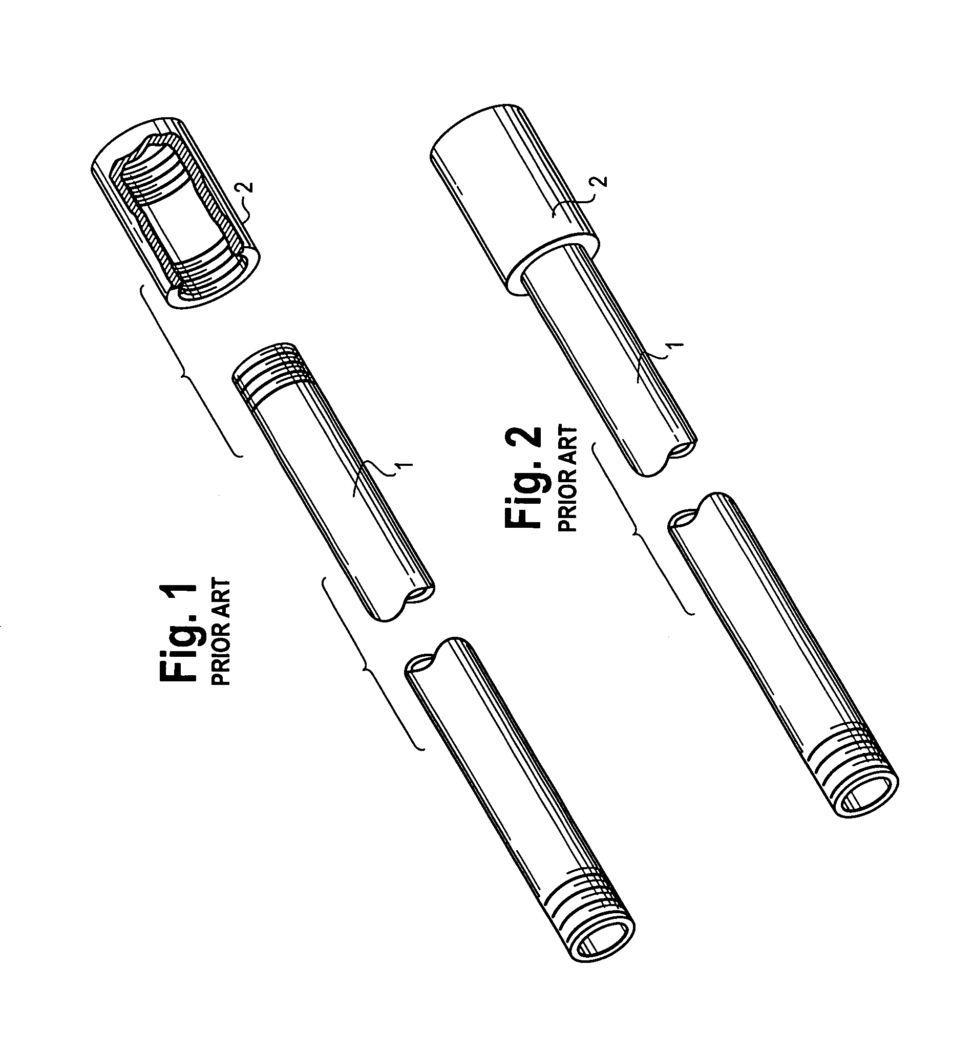
CROSS-REFERENCE TO RELATED APPLICATION[0001]This application claims the benefit of U.S. Provisional Application Ser. No. 61 / 711,912, Oct. 10, 2012.FIELD OF THE INVENTION[0002]This invention relates to pipes and tubular conduits. More particularly, this invention relates to protectors for threaded pipe.BACKGROUND OF THE INVENTION[0003]Pipe having external threaded ends are manufactured in a wide variety of lengths, diameters, wall thicknesses, thread dimensions, and materials. The maximum length of individual sections of large diameter pipe for industrial use is generally about thirty to forty feet because of constraints in transporting the pipe from the point of manufacture to the point of use. When a very long pipe is needed, it is generally constructed by connecting multiple sections of pipe with short sleeves having internal threads known as couplings. It is common for pipe manufacturers to ship sections of pipe with a coupling already connected to one end (referred to herein as ...

Claims


Application Information

Patent Timeline
IPC IPC(8): F16L35/00F16L55/24F16L57/06F16L57/00F16L55/115F16L55/11
CPCF16L55/24F16L55/1108Y10T29/49826F16L55/1152F16L57/06F16L57/005Y10T29/4943B65D59/02B65D59/06
Inventor YODER, MICHAEL E.
Owner YODER MICHAEL E
Learn More