Oven door support legs

a technology for oven doors and legs, applied in the field of oven doors, can solve the problems of oven balance, entire oven inclination, serious burns, etc., and achieve the effects of simple and efficient installation, protection, and appearan

Inactive Publication Date: 2015-10-13
DRAPER RICHARD J
View PDF29 Cites 9 Cited by
  • Summary
  • Abstract
  • Description
  • Claims
  • Application Information

AI Technical Summary

Benefits of technology

[0008]In view of the foregoing references, the inventor recognized the aforementioned inherent problems and observed that there is a need for a simple oven door support leg device providing necessary adjustment features while providing simple and efficient installation, operation, protection, and appearance. Thus, the object of the present invention is to solve the aforementioned disadvantages and provide for this need.

Problems solved by technology

However, this can be dangerous if the foodstuff or cooking container is particularly heavy.
Objects such as heavy roasts or large baking dishes can inadvertently upset the balance of the oven and cause the entire oven to tip forward.
If any items are on top of the stove at this time, injuries and serious burns can result.
However, not using the door is unfavorable because the use of the door allows physically disadvantaged persons such as the elderly, disabled, or weak in stature to place and lift a heavy object in an easier and safer manner.
While these devices fulfill their respective, particular objectives, each of these references suffer from one (1) or more of the aforementioned disadvantages.
Many such devices do not provide a simple deployment mechanism.
Also, many such devices do not provide sufficient and simple adjustment features.
Furthermore, many such devices do not provide simple installation to an existing oven door.
In addition, many such devices may damage an oven door or floor surface during installation and use.
Moreover, many such devices severely impact the aesthetic qualities of an oven and a kitchen as a whole.

Method used


Image

  • Oven door support legs
  • Oven door support legs
  • Oven door support legs

Examples


Embodiment Construction

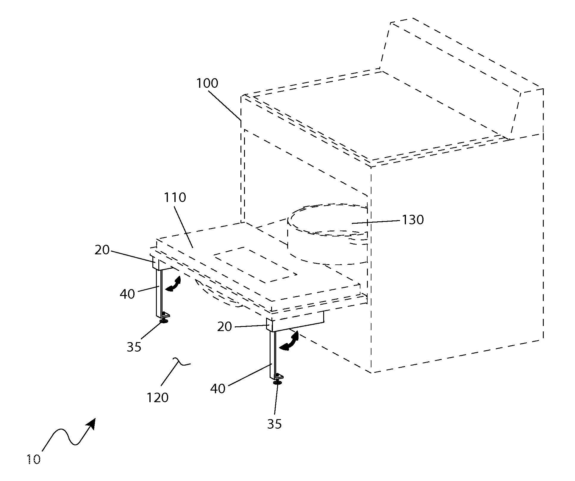
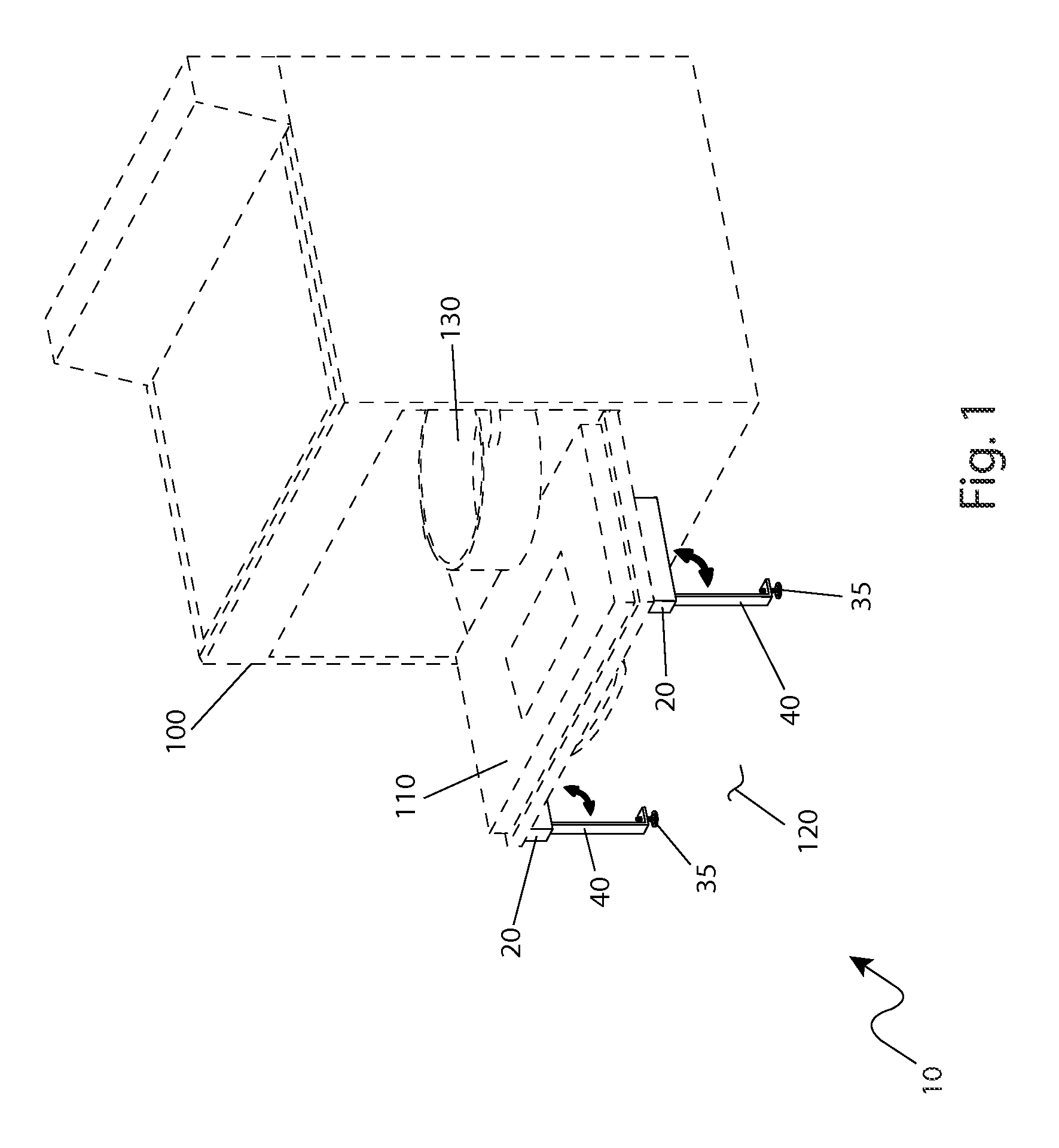
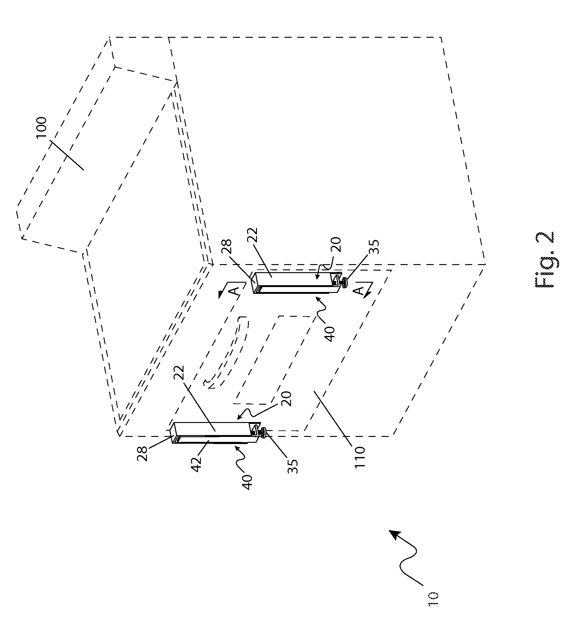
[0045]The best mode for carrying out the invention is presented in terms of its preferred embodiment, herein depicted within FIGS. 1 through 4. However, the invention is not limited to the described embodiment and a person skilled in the art will appreciate that many other embodiments of the invention are possible without deviating from the basic concept of the invention, and that any such work around will also fall under scope of this invention. It is envisioned that other styles and configurations of the present invention can be easily incorporated into the teachings of the present invention, and only one particular configuration shall be shown and described for purposes of clarity and disclosure and not by way of limitation of scope.

[0046]The terms “a” and “an” herein do not denote a limitation of quantity, but rather denote the presence of at least one of the referenced items.

[0047]The present invention describes a pair of oven door support legs (herein described as the “apparat...


PUM


Abstract

A pair of self-folding legs intended to support a door of an oven when in an open position pivot downwardly from a front surface of the door to a floor surface, thus forming a stable support system. In such a manner, heavy objects can be placed on the door surface as they enter and exit the oven cavity. The pair of legs is fastened to the front surface of the door using a high-temperature adhesive fastening method. The legs automatically pivot down as the door is opened and fold back up when the door is closed. Each leg comprises a height adjustable foot with a rubberized bottom surface to accommodate all styles and sizes of ovens to avoid damage to the floor surface.

Description

RELATED APPLICATIONS[0001]The present invention was first described in and claims the benefit of U.S. Provisional Application No. 61 / 307,020 filed Feb. 23, 2010, the entire disclosures of which are incorporated herein by reference.FIELD OF THE INVENTION[0002]The present invention relates generally to oven doors, and in particular, to legs supporting an oven door.BACKGROUND OF THE INVENTION[0003]Residential ovens are one (1) of the most oft-utilized appliances in the preparation of meals on a day-to-day basis. These ovens, typically located within a kitchen in a home, are generally located along a ground surface and provide a large interior space capable of holding more food and reaching higher temperatures than most other residentially available cooking appliances such as toasters or microwaves.[0004]Due to their size, most ovens have large doors which hinge down and out from the oven structure. These doors typically stop at a position parallel to the ground surface and several inch...

Claims


Application Information

Patent Timeline
Patent Type & Authority Patents(United States)
IPC IPC(8): F24C15/02A47B3/08A47B5/06F24B1/192F24B13/00A47B5/00F16M11/16
CPCF24C15/026A47B3/08F24C15/023F24C15/028F16M11/16A47B5/00F24B13/004F24C15/02
Inventor DRAPER, RICHARD J.
Owner DRAPER RICHARD J
Why Eureka
Try Eureka