Illuminated decorative part

a technology for decorative parts and lighting, applied in interior lighting, dashboard lighting devices, transportation and packaging, etc., can solve the problems of limiting the optical brilliance that can be achieved with the decorative lighting unit according to the generic prior, requiring a relatively large design, and reducing the chance of light loss, etc., to achieve the effect of simple production, reduced chance, and compact construction

Active Publication Date: 2020-06-30
DAIMLER AG
View PDF32 Cites 0 Cited by
  • Summary
  • Abstract
  • Description
  • Claims
  • Application Information

AI Technical Summary

Benefits of technology

[0004]The problem addressed by the present invention thus involves an illuminated decorative part that can be constructed to be very compact, especially in its overall height in the direction in which the light is emitted, and that nevertheless permits a very brilliant and high-contrast emission of light.
[0032]The design of the optical decorative part 4 in the embodiments described can then be constructed extraordinarily compactly in the Y direction, since the individual layers themselves can be made very thin, and since the space a can be selected to be relatively small in order to achieve the desired optical effect. The individual stripes 6, 7, 8 or other geometric patterns or (written) symbols can accordingly be produced by the light guides 15, wherein other shapes, figures and so on can also be represented on the visible side 10 of the illuminated decorative part 4, depending upon the configuration and size of the light guides. The activation of the light-emitting diodes 12, which are preferentially arranged in the form of a matrix on the support element 11, can be freely programmable by an electronic control device in a manner that is known per se with respect to the intensity, light color, representation of chases or the like. The very compact design is simple to produce and install, for example by providing the support element 11 with a plate that has the matrix of the light-emitting diodes 12. At the same time, the decorative layer 14 is sprayed onto the scattering element 13, and the light guides 15 are connected, e.g., adhered, to the scattering element 13 in the required positions. This structure can then be mechanically clipped, for example, to the support element 11 in order to achieve a simple and efficient installation. The illuminated decorative part 4 obtained in this way, for instance, a decorative stripe for the vehicle dashboard 1, can then be installed in the vehicle as a whole component and must only be wired within the vehicle dashboard to provide power to the light-emitting diodes 12. However, this wiring can also include a connection to the appropriate control device so that the desired optical representation, such as to support the ambient lighting of the vehicle interior with a high level of optical brilliance and quality, can be implemented according to a predetermined or selectable illumination concept.

Problems solved by technology

The design of the decorative lighting unit in the generic prior art has the disadvantage that, due to the lens and the inserted stripe image in the interior of the decorative lighting part, it requires a relatively large design in the direction of the light emission, i.e. substantially orthogonally to the surface facing the observer of the decorative lighting part.
This is disadvantageous for use, for example, in the area of a dashboard of a motor vehicle, since the available installation space here is typically very limited in the depth direction.
A further disadvantage consists in the fact that a stripe image is required in order to represent the desired display.
Typically, this stripe image is transilluminated in the manner of a transparent photo slide, which leads to a not insignificant loss of light, and which correspondingly limits the optical brilliance that can be achieved with the decorative lighting unit according to the generic prior art.
For example, it can consist of a sufficiently ductile material to ensure crash safety for use in a vehicle despite the use of the optically very high-grade PMMA, which alone would not provide any crash safety.

Method used


Image

  • Illuminated decorative part
  • Illuminated decorative part
  • Illuminated decorative part

Examples


Embodiment Construction

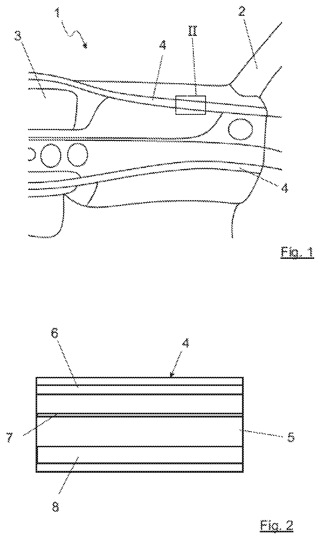
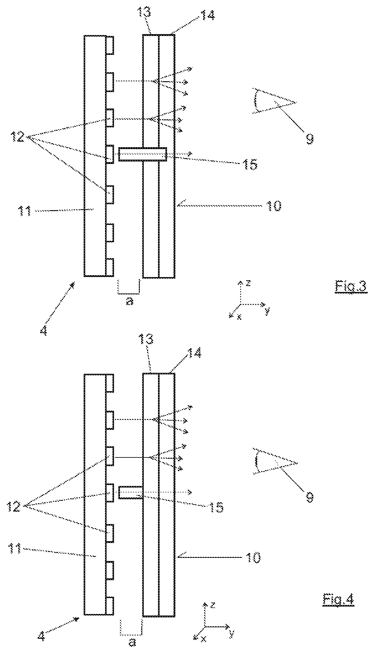
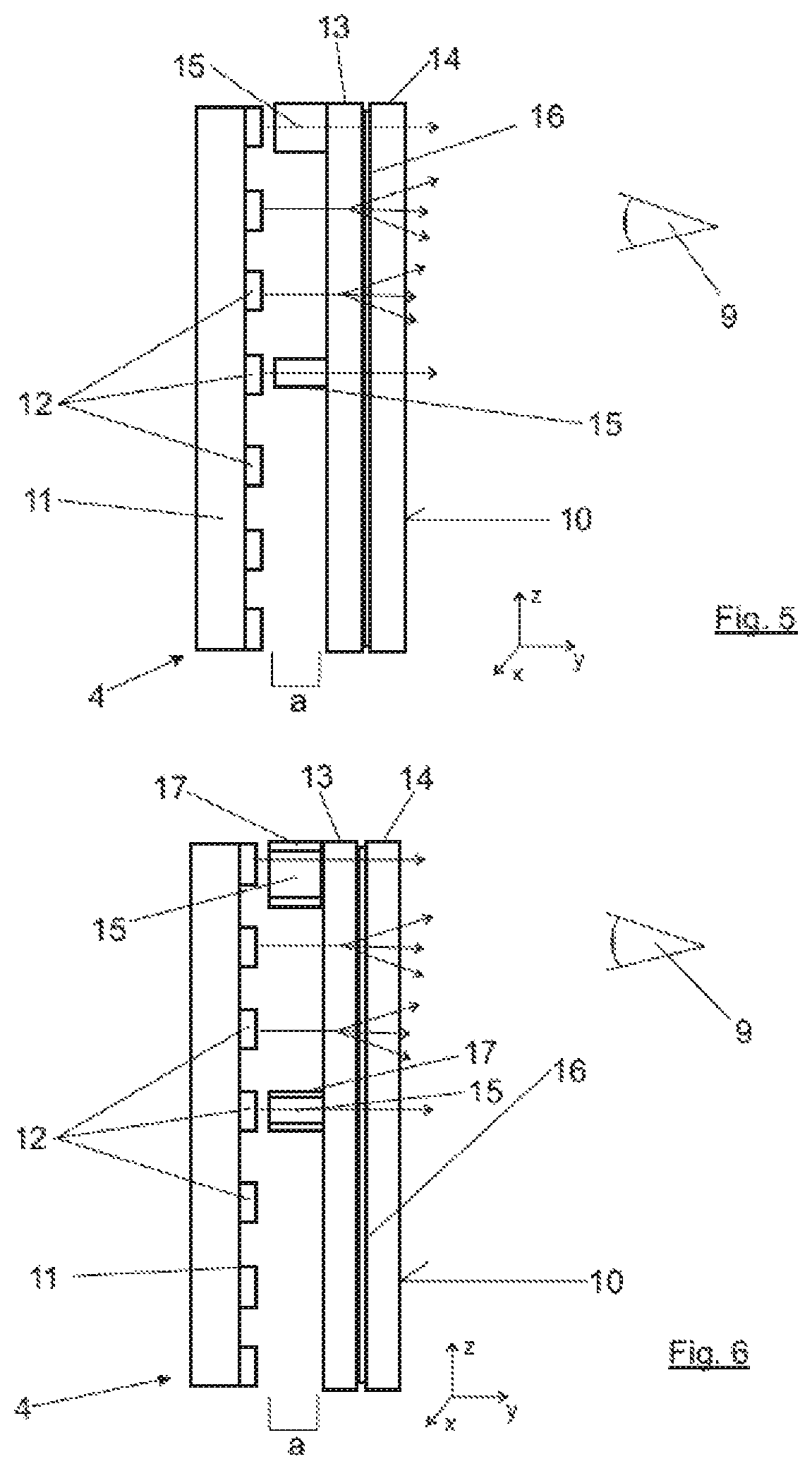
[0024]A section of a dashboard 1 of a vehicle, which is not shown in its entirety, can be discerned in the drawing in FIG. 1. This section substantially shows the region of the dashboard 1 in front of the so-called passenger seat between an exemplarily shown A-pillar 2 of the vehicle and a display 3, which can be discerned on the left edge of the image and which should be a part of the central console of the vehicle. Two exemplary illuminated decorative parts are arranged in the vicinity of the dashboard, each of which is identified with 4 and which are configured here as continuous decorative stripes running through the vehicle dashboard 1 transverse to the driving direction. These illuminated decorative parts 4, the structural details of whose design will be discussed later, are typically configured with a flat and thus lightly curved surface, which is normally convexly curved toward the observer. For the sake of simplification, the discussion that follows is of a flat surface, ev...


PUM

PropertyMeasurementUnit
transparentaaaaaaaaaa
translucentaaaaaaaaaa
non-transparentaaaaaaaaaa

Abstract

An illuminated decorative part includes a flat visible side facing an observer and an illumination region behind the visible side as viewed by the observer, which has multiple discrete light sources. At least partially transparent optical elements that influence the light are arranged between the visible side and the illumination region. The optical elements include at least one flat scattering element. The decorative part includes light guides for guiding the light orthogonally to the surface of the visible side arranged between the scattering element and at least one—but not all—of the light sources.

Description

BACKGROUND AND SUMMARY OF THE INVENTION[0001]The invention relates to an illuminated decorative part.[0002]Illuminated decorative parts, in particular for adjustable ambient lighting within a vehicle, are known from the prior art. Patent DE 10 2009 030 684 A1 by the applicant relates to a decorative element of this type, which has a transparent top layer, into which light can be coupled. Corresponding cut-outs can then be provided in an applied decorative film in order to emit the light through them, in particular into the interior compartment of a vehicle that is equipped with the decorative element.[0003]An illuminated decorative part of the type in question is known by the term ‘decorative lighting unit’ from DE 10 2010 055 129 A1. The decorative lighting unit consists of a support that is provided with light sources, an optical element in the form of an optical lens, and a diffusor and a mask. A stripe image or another type of image display is inserted between the diffusor and t...

Claims


Application Information

Patent Timeline
Patent Type & Authority Patents(United States)
IPC IPC(8): B60Q3/00B60Q3/64B60Q3/60B60Q3/66B60Q3/78B60Q3/14B60Q3/54B60R13/02B60Q3/74
CPCB60Q3/14B60Q3/54B60Q3/64B60Q3/74B60Q3/78B60R13/0256B60Q3/60B60Q3/66B60R2013/0287B60Q2500/10B60Q2900/40
Inventor BETZ, CHRISTIANBETZ, DANIELBOROWSKI, MARTINMOSER, KEVIN
Owner DAIMLER AG
Why Eureka
Try Eureka