Wall adaptor

a wall adaptor and adapter technology, applied in the direction of electrical apparatus casing/cabinet/drawer, arrangement using take-up reel/drum, coupling device connection, etc., can solve the problems of lack of adaptability, inability to replace the adaptor according to the user, extra burden on the user, etc., to relieve the financial burden on the consumer, improve adaptability, and reduce the effect of cos

Inactive Publication Date: 2015-10-13
LIAO SHENG HSIN
View PDF15 Cites 31 Cited by
  • Summary
  • Abstract
  • Description
  • Claims
  • Application Information

AI Technical Summary

Benefits of technology

[0008]The instant disclosure provides a wall adaptor suitable to different types of connector modules and therefore has better adaptability which is more convenient. The adaptor main body needs not to be changed, such that the cost is reduced, and the financial burden on the consumer is relieved.
[0012]The connector module is detachably disposed on the connector body, such that different connector modules can be used so as to improve the adaptability. In this way, the wall adaptor is more convenient in practical use. The adaptor body does not need to be changed, such that the cost is reduced and the consumer does not need to buy additional adaptors.
[0013]The wall adaptor may also include a load plate for carrying an electronic product. The load plate accommodates the electronic product under charge or signal transmission through the wall adaptor, protects the electronic product and maintains practical usage under charge and signal transmission when in operation.

Problems solved by technology

Therefore, the connector cannot be replaced according to user need, which lacks in adaptability.
If a user is going to use another type of connector, a new type of charger has to purchased, which cause extra burden to the user.
Furthermore, the charger (adaptor) has limited functions without the service of carrying an electronic product.

Method used


Image

  • Wall adaptor
  • Wall adaptor
  • Wall adaptor

Examples


first embodiment

[0036][First Embodiment]

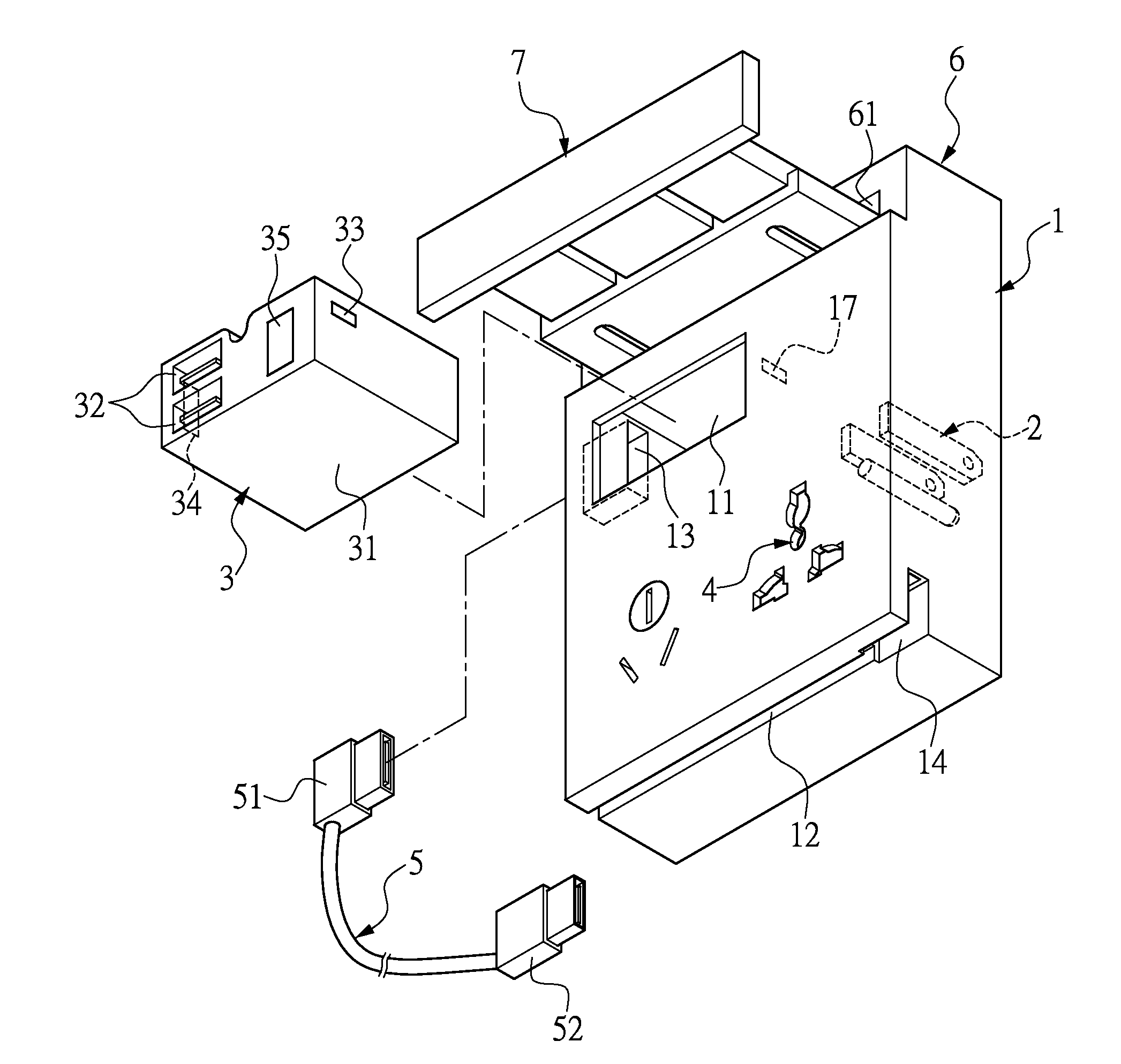
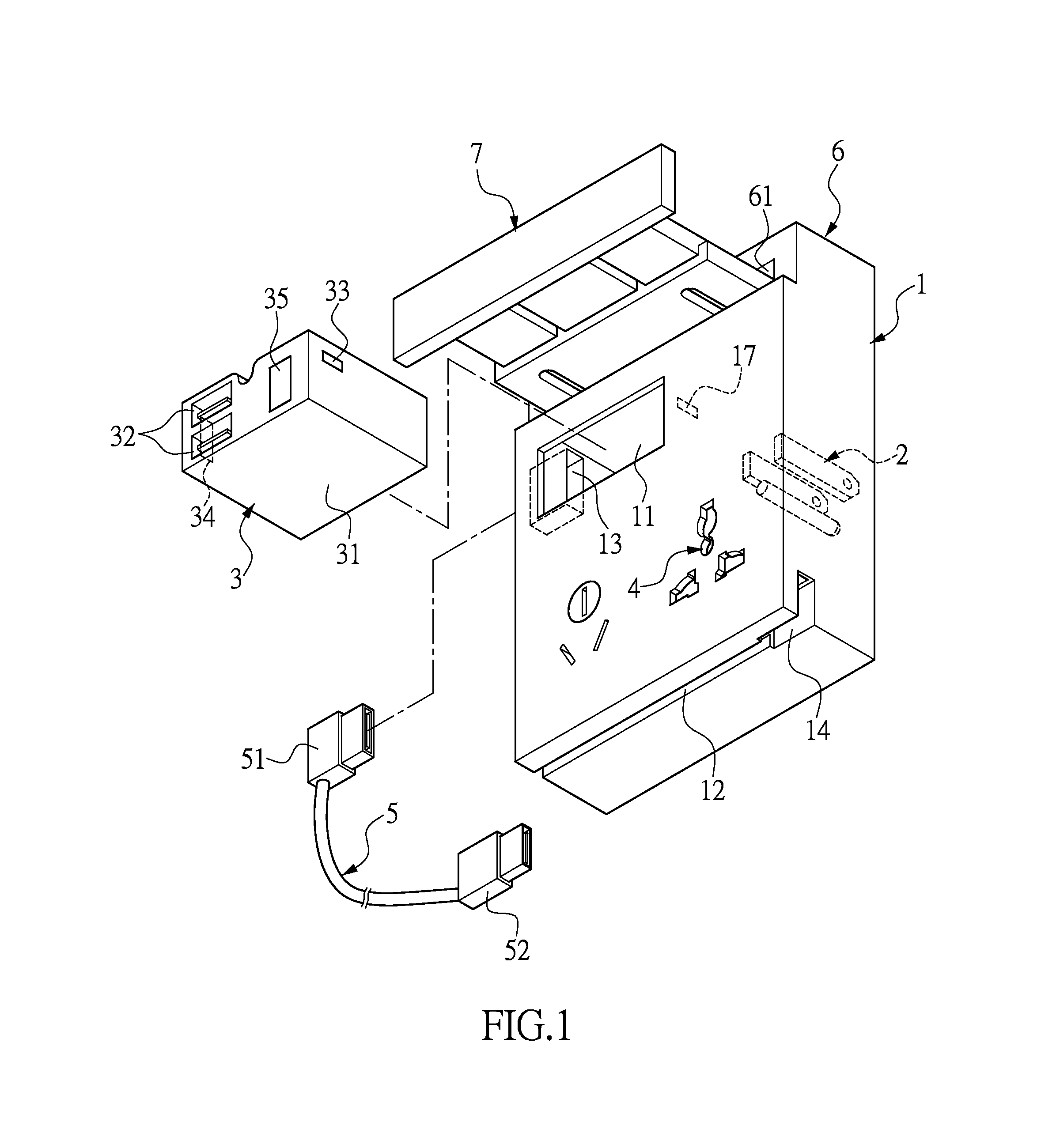
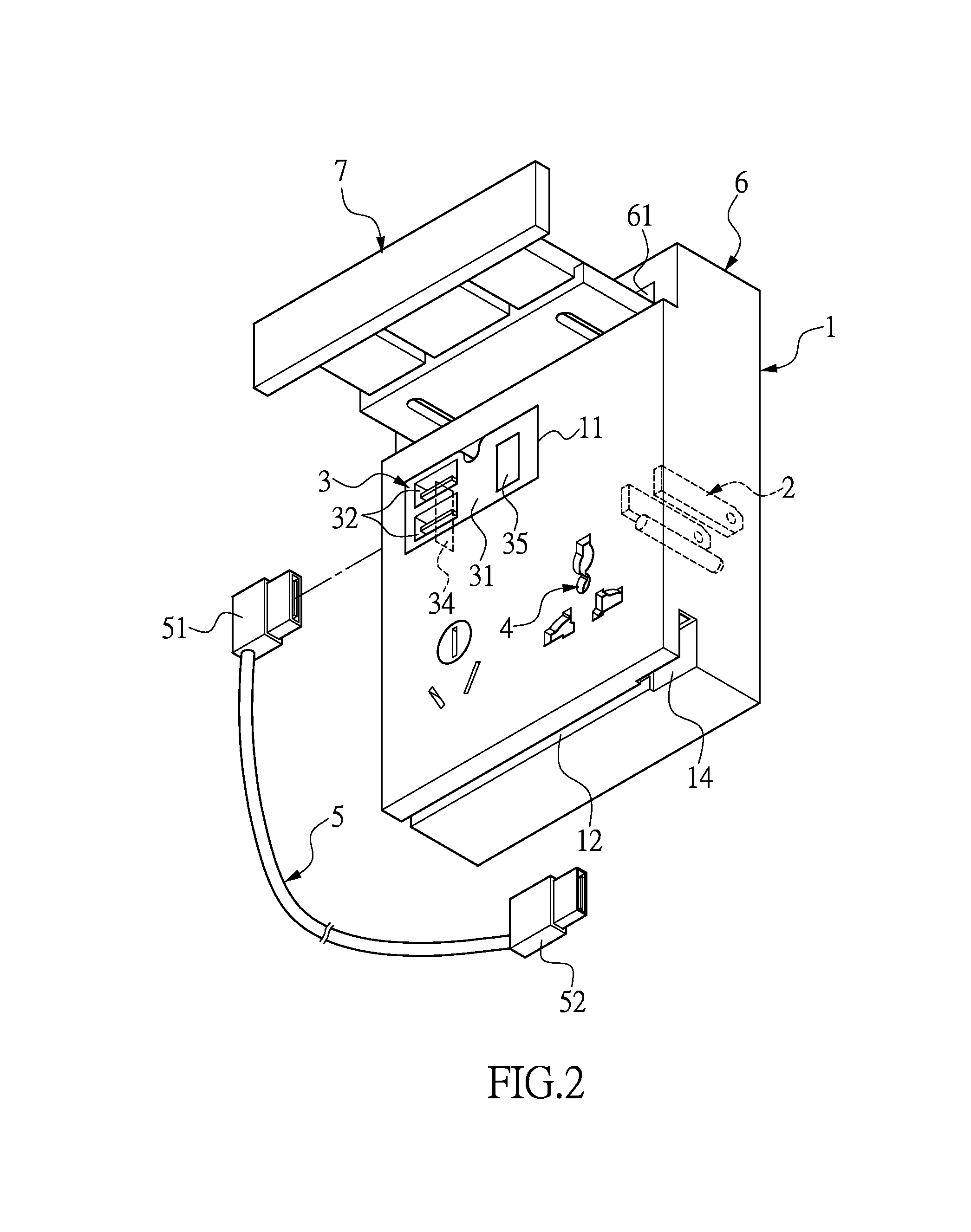
[0037]Please refer to FIGS. 1 and 2. The instant disclosure provides a wall adaptor. The wall adaptor can be plugged to a wall receptacle or the like. The interior of the wall adaptor may further have charging circuit (not shown) to serve as a charger. The charging circuit is known to a person skilled in the art, and herein it is not repeated. If charging is not required from the wall adaptor, the charging circuit can be omitted in the instant embodiment.

[0038]The wall adaptor includes an adaptor body 1, a terminal unit 2 and at least one connector module 3. The configuration of the adaptor body 1 is not limited to a plate, a block, or any other geometrical configuration, and the adaptor body 1 may have different configurations according to design requirements. The adaptor body 1 may be integrally formed, two-piece or multiple-piece. The adaptor body 1 may also have a receptacle unit 4. The standard and configuration of the receptacle unit 4 are not limited t...

second embodiment

[0054][Second Embodiment]

[0055]Please refer to FIG. 4. In the instant embodiment, the abovementioned receiving box 6 and the load plate 7 are omitted, such that the overall wall adaptor configuration is simplified.

third embodiment

[0056][Third Embodiment]

[0057]Please refer to FIG. 5. In the instant embodiment, the adaptor body 1b is pivotally connected to a load plate 7. In other words, the adaptor body 1b has a first pivot portion 15, and one side of the load plate 7 has a second pivot portion 71. The first pivot portion 15 and the second pivot portion 71 are corresponding pivot hole and pivot shaft. The first pivot portion 15 and the second pivot portion 71 are pivotally connected to each other, such that the load plate 7 may flap in relation to the adaptor body 1b. However, the connection method between the load plate 7 and the adaptor body 1b is not limited thereto, any shaft, pivot or chain being acceptable. The load plate 7 may flap downward to a horizontal position for receiving the electronic product, whereas the load plate 7 may flap upward so as to be stacked on the front of the adaptor body 1b. The edge of the load plate may also have a latch 72, such that when the load plate 7 flaps upward, the la...


PUM


Abstract

A wall adaptor includes an adaptor body, a terminal unit and a connector module. The terminal unit is disposed on the adaptor body and has a pin arrangement, and the connector module is detachably disposed on the adaptor body. The connector module has a module body and at least a first connector disposed on the adaptor body, the connector module and the adaptor body are in electrical communication through electrical contacts. The connector module is replaceable for broader implementation.

Description

BACKGROUND[0001]1. Field of the Invention[0002]The instant disclosure relates to a wall adaptor; in particular, to a wall adaptor fixed on a wall receptacle or the like.[0003]2. Description of Related Art[0004]Conventional utility planning and design for interiors usually involves embedment in the wall and connection to the receptacle on the wall for electricity or signal transmission. When an electronic product (for example, mobile phone, digital camera, personal digital assistance or other portable electronic device) runs low in power and needs supplement electricity to maintain operation, recharge or signal transmission is done by wire connection, a user can connect the electronic product to electricity or signal wiring through a cable with a head plugging into the receptacle so as to obtain power or connect to the Internet.[0005]U.S. Pat. No. 8,415,920 by the present applicant disclosed a charger and a combination structure. One side of the charger is formed with terminals. The ...

Claims


Application Information

Patent Timeline
Patent Type & Authority Patents(United States)
IPC IPC(8): H01R13/60H05K5/00
CPCH05K5/0065H02G3/16H02G3/18H02G11/02H01R13/72H01R25/003H01R25/006H01R27/02H01R31/065H02J7/0044
Inventor LIAO, SHENG-HSIN
Owner LIAO SHENG HSIN
Why Eureka
Try Eureka