Super wide angle lens and imaging apparatus

a wide angle lens and imaging apparatus technology, applied in the field of super wide angle lenses and imaging apparatuses, can solve the problems of heavy focusing group, achieve excellent images, reduce performance and angle of view fluctuations, and accelerate focusing

Active Publication Date: 2015-10-20
FUJIFILM CORP
View PDF19 Cites 11 Cited by
  • Summary
  • Abstract
  • Description
  • Claims
  • Application Information

AI Technical Summary

Benefits of technology

[0008]The present invention has been developed in view of the above circumstances. It is an object of the present invention to provide a super-wide-angle lens having a smaller F-number and high optical performance, in which reduction in weight of a focusing group is achieved and fluctuations in aberrations and fluctuations in the angle of view during focusing are reduced; and an imaging apparatus equipped with such a super-wide-angle lens.
[0027]conditional expressions (1) and (2) are satisfied.This enables a small F-number, a super wide angle, and high performance of the lens as well as enabling reduction in weight of a focusing group and suppression of fluctuations in aberrations and fluctuations in the angle of view while focusing.
[0028]Further, since the imaging apparatus according to the present invention includes the super-wide-angle lens of the present invention, the imaging apparatus allows photography even under low illuminance conditions, can obtain excellent images with a wide angle of view, enables rapid focusing with respect to a subject which is moving, and can reduce fluctuations in performance and fluctuations in the angle of view while focusing.

Problems solved by technology

However, the lens system disclosed in Japanese Unexamined Patent Publication No. 2011-186269 cannot necessarily be suitable for use in movie cameras because the lens system is mainly designed to be as a projection lens and is a floating focus system that moves two lens groups in different paths, and thereby there is a possibility that the focusing groups will be heavy.

Method used


Image

  • Super wide angle lens and imaging apparatus
  • Super wide angle lens and imaging apparatus
  • Super wide angle lens and imaging apparatus

Examples


example 1

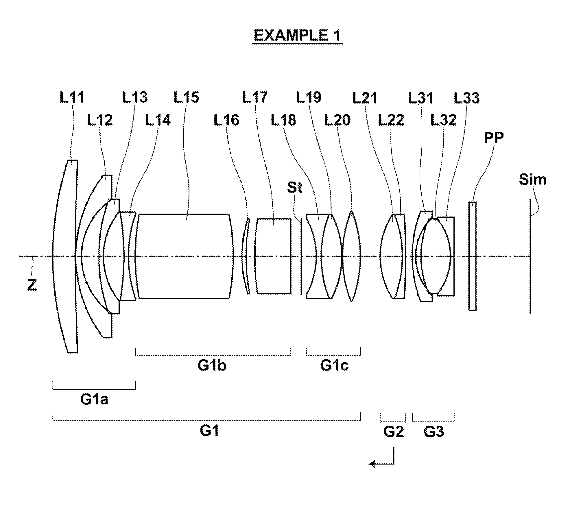
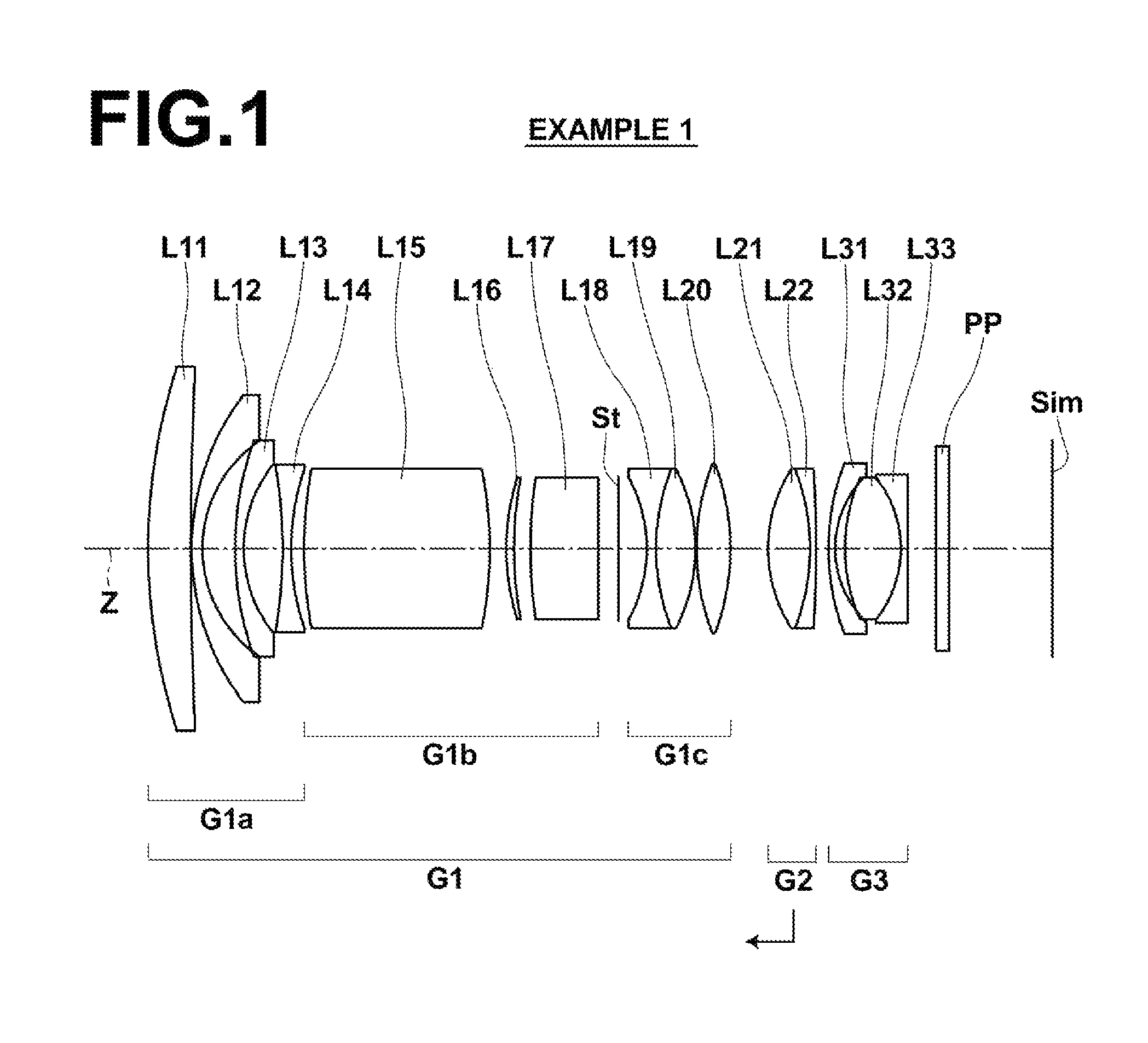
[0078]FIG. 1 shows the lens configuration of the super-wide-angle lens of Example 1. The manner in which the drawing is shown has been given above, and accordingly redundant descriptions thereof will be omitted.

[0079]The super-wide-angle lens of Example 1 is schematically configured as shown below. That is, the super-wide-angle lens consists of a first lens group G1 having positive refractive power, a second lens group G2 having positive refractive power, and a third lens group G3 having negative refractive power in this order from the object; the first lens group G1 consists of a first sub lens group G1a having negative refractive power, a second sub lens group G1b having positive refractive power, an aperture stop St, and a third sub lens group G1c having positive refractive power in this order from the object side; the first lens group G1 and the third lens group G3 are fixed while focusing; and the second lens group G2 moves toward the object side while focusing from an object a...

example 2

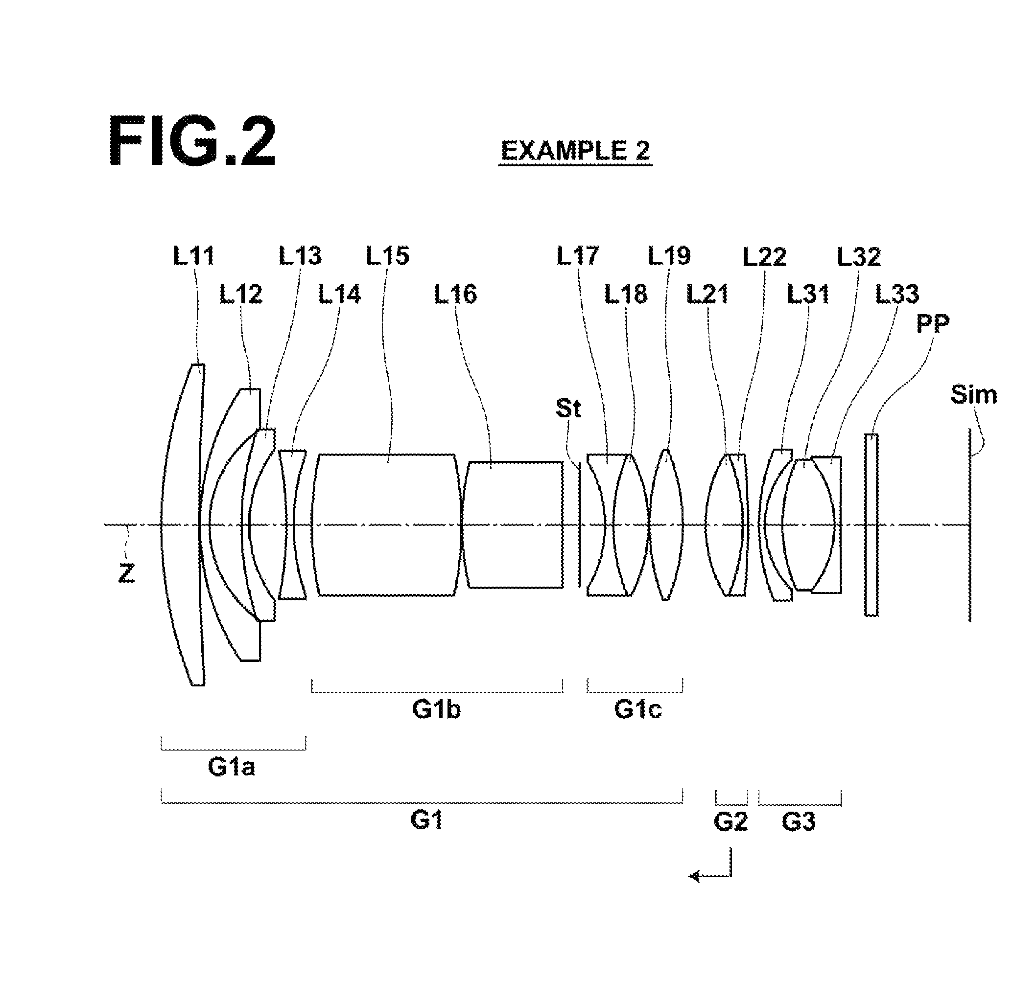
[0089]FIG. 2 is a lens configuration diagram of the super-wide-angle lens of Example 2. The schematic configuration of the super-wide-angle lens of Example 2 is the same as that of Example 1.

[0090]However, in the super-wide-angle lens of Example 2, the first sub lens group G1a consists of lenses L11 through L14, the second sub lens group G1b consists of lenses L15 and L16, the third sub lens group Glc consists of lenses L17 through L19, the second lens group G2 consists of lenses L21 and L22, and the third lens group G3 consists of lenses L31 through L33.

[0091]Table 2 shows lens data of the super-wide-angle lens of Example 2. A through E of FIG. 6 respectively show aberration diagrams of the super-wide-angle lens of Example 2.

[0092]

TABLE 2Example 2f = 1.000, FNo. = 2.1, 2ω = 89.8°SiRiDiNdjνdj 14.6221460.40301.5163364.14 225.0295590.0084 32.6304750.10191.8502632.27 41.2337310.3431 53.1943440.08051.8466623.78 61.3269580.3979 7−3.9388200.07951.6204160.29 82.3188240.1910 93.4590061.5999...

example 3

[0093]FIG. 3 is a lens configuration diagram of the super-wide-angle lens of Example 3. The schematic configuration of the super-wide-angle lens of Example 3 is the same as that of Example 1.

[0094]However, in the super-wide-angle lens of Example 3, the first sub lens group G1a consists of lenses L11 through L13, the second sub lens group G1b consists of lenses L14 through L16, the third sub lens group G1c consists of lenses L17 through L19, the second lens group G2 consists of lenses L21 and L22, and the third lens group G3 consists of lenses L31 through L33.

[0095]Table 3 shows lens data of the super-wide-angle lens of Example 3. A through E of FIG. 7 respectively show aberration diagrams of the super-wide-angle lens of Example 3.

[0096]

TABLE 3Example 3f = 1.000, FNo. = 2.0, 2ω = 91.0°SiRiDiNdjνdj 13.3069680.43151.7880047.37 27.6475960.0084 32.7685250.10141.6204160.29 41.2273720.4262 55.6078100.08001.8466623.78 61.1880960.4781 7−2.7564111.22741.4874970.23 8−2.1857900.0112 91.7753670....


PUM


Abstract

This super-wide lens substantially consists of a positive first lens group, a positive second lens group, and a negative third lens group, in this order from the object side. The first lens group and the third lens group are fixed and the second lens group moves toward the object side while focusing from an object at infinity to an object at the closest distance. The first lens group substantially consists of a negative first sub lens group, a positive second sub lens group, an aperture stop, and a positive third sub lens group in this order from the object side. Conditional expressions (1) and (2) are satisfied:0.15<f1 / f2<0.60  (1)2.5<f2 / f<7.0  (2), wheref1: the focal length of the first lens group,f2: the focal length of the second lens group, andf: the focal length of the entire system when focusing on an object at infinity.

Description

CROSS-REFERENCE TO RELATED APPLICATIONS[0001]This application is a Continuation of PCT International Application No. PCT / JP2013 / 000516 filed on Jan. 31, 2013, which claims priority under 35 U.S.C. §119 (a) to Japanese Patent Application No. 2012-022934 filed on Feb. 6, 2012. Each of the above application (s) is hereby expressly incorporated by reference, in its entirety, into the present application.BACKGROUND OF THE INVENTION[0002]1. Technical Field[0003]The present invention relates to a super-wide-angle lens and an imaging apparatus, and more particularly to a super-wide-angle lens which can be used for a digital camera, a broadcasting camera, a movie camera, and the like; and an imaging apparatus including the super-wide-angle lens.[0004]2. Description of the Related Art[0005]In recent years, there is great demand for cameras in the above fields to have a small F-number which enables photography in dark places and to have high performance which can be compatible with recent high...

Claims


Application Information

Patent Timeline
Patent Type & Authority Patents(United States)
IPC IPC(8): G02B15/14G02B13/04G02B9/12G02B13/06
CPCG02B13/04G02B9/12G02B13/06
Inventor ONO, KAZUNORI
Owner FUJIFILM CORP
Why Eureka
Try Eureka